Figure 18, Evaluation board user guide ug-001 – Analog Devices UG-001 User Manual
Page 11
Evaluation Board User Guide
UG-001
Rev. 0 | Page 11 of 24
0
77
82
-02
9
07
78
2-
03
0
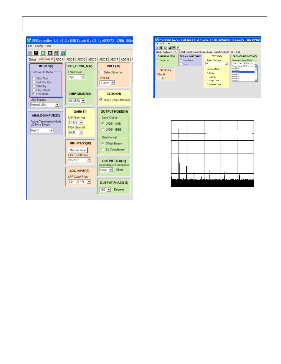
Figure 19. SPI Controller, CROSSPOINT SWITCH(2D) Box
8. Examine the spectrum analyzer for the CW Doppler output
(see Figure 20 for an example).
0
–10
–20
–30
–40
–50
–60
–70
–80
–90
–100
0
2
0
778
2-
0
04
FREQUENCY (MHz)
AM
P
L
IT
UDE
(
d
Bm)
5
10
15
20
5
FREQUENCY = 2.3MHz
CWD1±, DIFFERENTIAL OUTPUT
Figure 20. Typical Spectrum Analyzer Display of CWD Output
Figure 18. SPI Controller, MODES(8) Box
7. In the ADC x tab of the SPI Controller, where x is the channel
to which an analog input is applied, find the CROSSPOINT
SWITCH(2D)
box. From the Crosspoint Switch Modes
drop-down box, select the cwd2p/n option (see Figure 19).