Front panel headers: sw/led, speaker, Sata ii connector: sata1/sata2/sata3/sata4 – Albatron Technology KI51PV-754 User Manual
Page 16
Mainboard KI51PV-754
12
SATA II Connector: SATA1/SATA2/SATA3/SATA4
The four SATA II connectors support 3 Gbps transmit rate and RAID 0/1/ 0+1/ JBOD/ 5 mode.
One SATA II connector only can attach one SATA II HDD of each time using SATA cables.
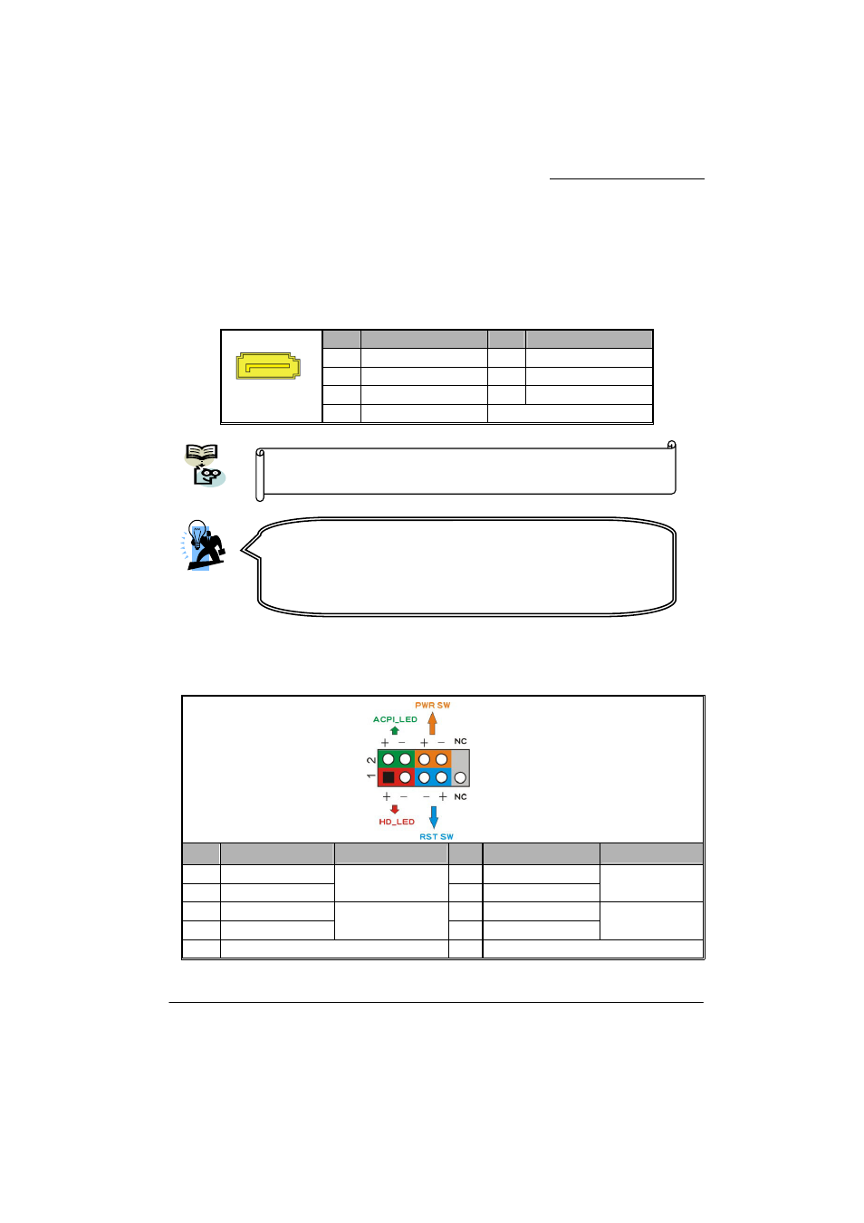
Front Panel Headers: SW/LED, SPEAKER
SW/LED
Pin
Assignment
Function
Pin
Assignment
Function
1
HDD LED (+)
2
Power LED (+)
3 HDD
LED
(-)
Hard Drive LED
(
HD_LED
)
4
Power LED (-)
Power LED
(
ACPI_LED
)
5
Reset Control (-)
6
Power Switch (+)
7 Reset
Control
(+)
Reset Switch
(
RST_SW
)
8 Power
Switch
(-)
Power-on Switch
(
PWR_SW
)
9 N/A 10
N/A
Pin
Assignment
Pin
Assignment
1 Ground
2 TX+
3 TX-
4 Ground
5 RX-
6 RX+
1
SATA1~4
7 Ground
This mainboard supports RAID 0/1/0+1/JBOD/5 modes, refer
Appendix II for more information.
Attention
The FDC/ IDE cable is designed and should be attached with a
specific direction. One edge of the cable will usually in color such
as red, to indicate that should line up with the header pin-1.