Rear panel, Understanding led indicators – Atlantis Land A02-F24-4G User Manual
Page 13
26-Port Dual Web Rack Switch
7
The Switch is equipped with two mini-GBIC ports, supported optional 1000BASE-SX/LX mini-GBIC
module (1000BASE-SX mini-GBIC module).
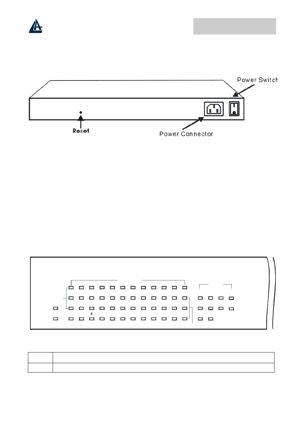
Rear Panel
Power Switch:
This is a switch where you can control to enable or disable the power.
AC Power Connector:
This is a three-pronged connector that supports the power cord. Plug in the female connector of the
provided power cord into this connector, and the male into a power outlet. Supported input voltages
range from 100-240V AC at 50-60Hz.
Reset:
The Reset button is to reset all the setting back to the factory default.
Note: Be sure that you recorded the setting of your device, else all the setting will be erased when
pressing the “Reset” button.
Understanding LED Indicators
The front panel LEDs provides instant status feedback, and, helps monitor and troubleshoot when
needed.
1
POWER
SYSTEM
2
3
4
5
6
7
8
9
10
11 12 13 14 15 16
24-Port 10/100MbpsEthernet SmartSwitch
Link/ACT
FDX
17 18 19
20 21 22 23 24
FX
28-Port 10/100/1000Mbps Web-SMART Gigabit Ethernet Switch
2
POWER
SYSTEM
4
8
10
12
14
16
18
20
22
24
1
3
5
7
9
11
13
15
17
19
21
23
25
26
27
28
Link/ACT
1000Mbps
100Mbps
10/100M
100Mbps
Link/ACT
Gigabit
Led POWER
On
: When the Power LED lights on, the Switch is receiving power.
Off
: When the Power turns off or the power cord has improper connection..