3 general interface description – ACR Electronics Nauticast 2607 User Manual
Page 12
Installation Manual
8
Y1-03-0204 Rev.K
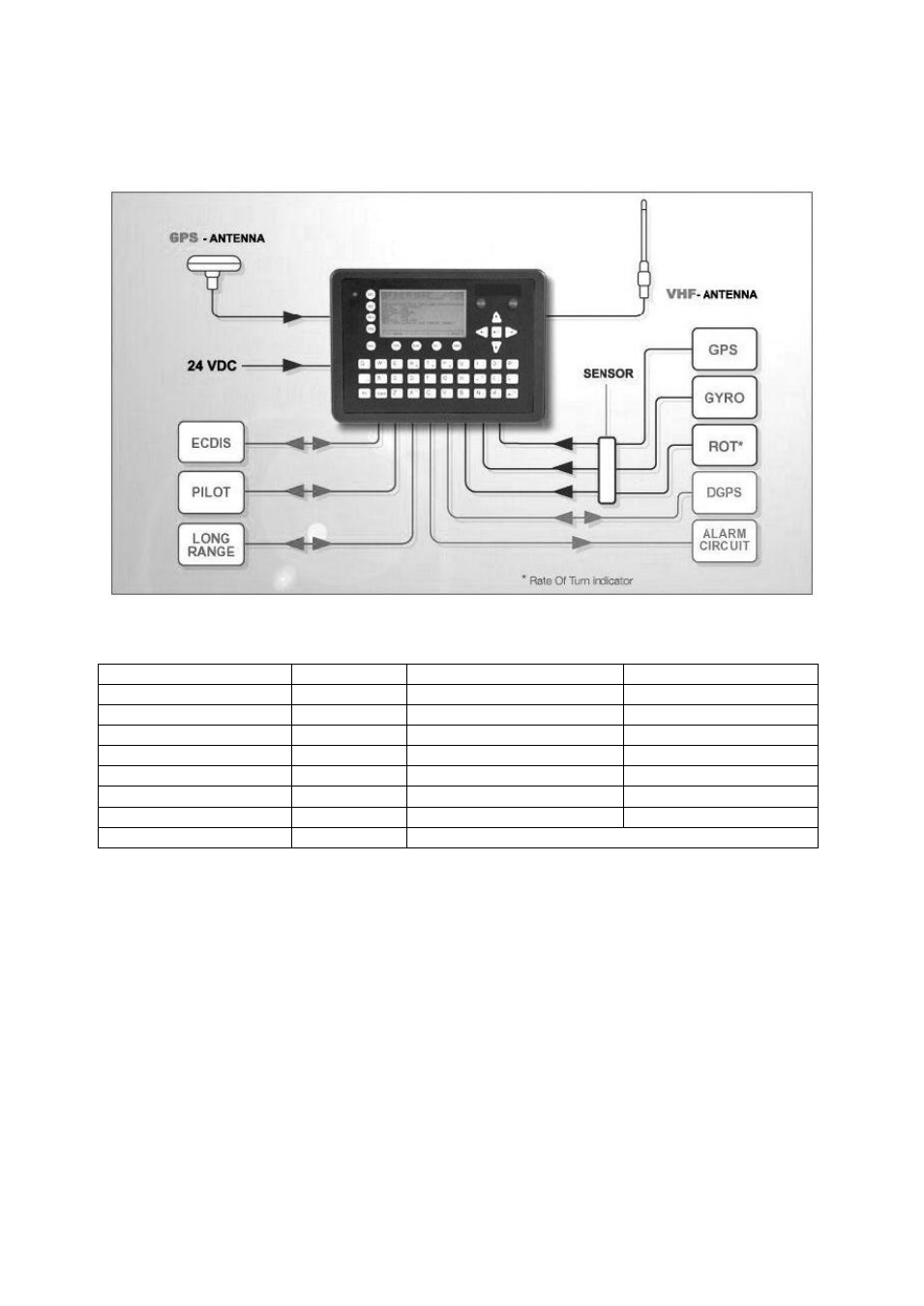
Components and Interfaces
The diagram below illustrates which devices can be connected to the NAUTICAST. For a
detailed description of sensor connecting e.g. an existing Gyro to the NAUTICAST refer to
Chapter 3.7
“Sensor Installation”.
3.3 General Interface Description
Interface
Designation Speed
Direction
Sensor 1
CH 1
4800bps or 38400bps
Input
Sensor 2
CH 2
4800bps or 38400bps
Input
Sensor 3
CH 3
4800bps or 38400bps
Input
ECDIS
CH 4
38400bps
Input/Output
PILOT
CH 5
38400bps
Input/Output
LONG RANGE
CH 8
38400bps
Input/Output
DGPS (RTCM SC104)
CH 9
9600bps
Input/Output
ALARM CIRCUIT
CH 10
Dry relay contact (power off and alarm state closed)
This manual is related to the following products: