Nilfisk-ALTO R 680 P User Manual
Page 74
ENGLISH
USER MANUAL
8
FLOORTEC R 680 P
1463514000(1)2008-05 A
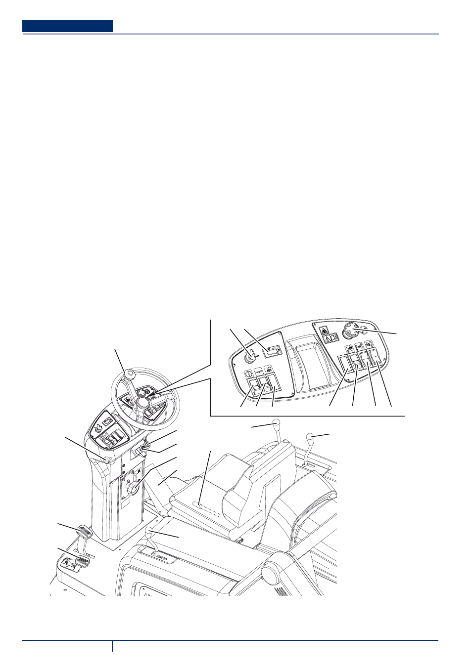
CONTROL PANEL
Hopper lifting/lowering/dumping enabling switch
61.
Horn switch
62.
Position for working light switch (optional)
63.
Main broom print adjusting knob
64.
Turn it counter-clockwise to increase the broom print
•
Turn it clockwise to decrease the broom print
•
Position for optional switch
65.
Switch
66.
(Lower position) vacuum system activation
67.
(Upper position) fi lter shaker activation
•
Hopper lifting/lowering switch
68.
Hopper dumping switch
69.
Ignition key
70.
When turned to “0”, it turns the engine off and disables
•
all functions.
When turned to “I”, it enables all machine functions; it
•
also turns on the fl ashing light.
When completely turned clockwise (“Start” position), it
•
starts the engine; when the engine is running release
the key, which returns to “I”.
Hour counter
71.
Emergency push-button. Press it in case of emergency to
72.
stop all the machine functions.
To deactivate the emergency push-button, turn it in the
73.
direction shown by the arrow.
Steering wheel
74.
Steering wheel tilting control knob
75.
Choke lever
76.
Parking brake lock control lever.
77.
It locks the service brake (82) thus switching it to parking
brake.
Forward/reverse gear pedal
78.
Right side broom lifting/lowering lever
79.
Left side broom lifting/lowering lever (optional)
80.
Seat longitudinal position adjusting lever
81.
Main broom lifting/lowering lever
82.
Front skirt lifting pedal
83.
Service brake pedal
84.
61 62
69
72
73
74
75
64
76
70
63
65
66
67 68
71
77
78
79
80
81
82
P100208