American Dryer Corp. MLG32PD3 User Manual
Page 25
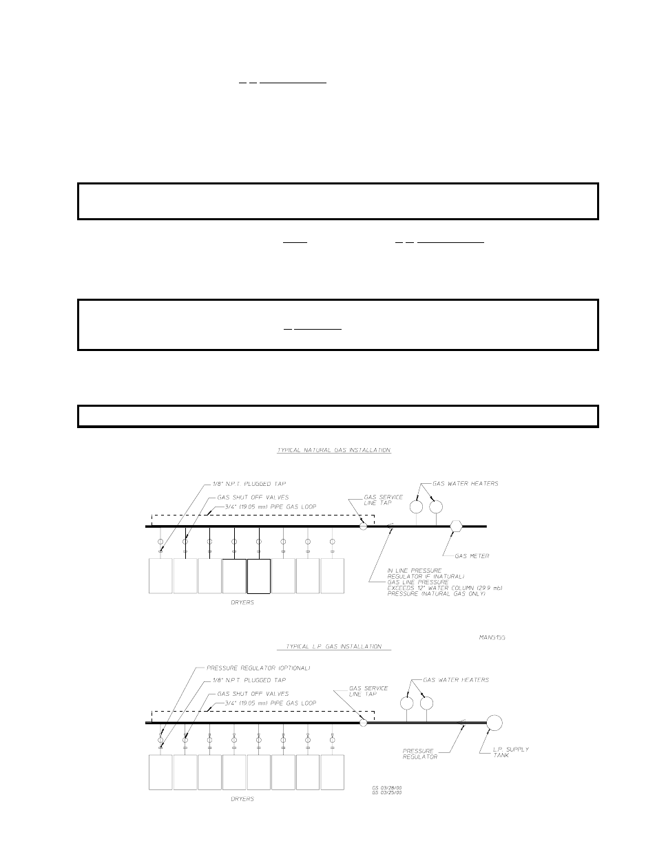
21
The dryer is provided with a 3/4” N.P.T. inlet pipe connection at the upper right hand corner (when viewed
from the rear) of each dryer. It is recommended that a gas shutoff valve be provided to the gas supply line
of each dryer for ease of servicing.
The size of the main gas supply line (header) will vary depending on the distance this line travels from
the gas meter (or in the case of liquid propane [L.P.] gas, the supply tank), the number of tees, other
gas-operated appliances on the supply line, etc. Specific information regarding supply line size should be
determined by the gas supplier.
NOTE: Undersized gas supply piping can create a low or inconsistent pressure which will result in
erratic operation of the burner ignition system.
Consistent gas pressure is essential at ALL gas connections. It is recommended that a 3/4” pipe loop be
installed in the supply line serving the bank of dryers. An in-line pressure regulator must be installed in the
gas supply line (header) if (natural) gas line pressure exceeds 12.0 inches water column (W.C.) - 29.9 mb
- pressure. (Refer to the illustration below for details.)
IMPORTANT: Water column pressure of 3.5 inches (8.7 mb) for natural gas dryers and 10.5 inches
(26.1 mb) for L.P. gas is required at the gas valve pressure tap of each dryer for
proper and safe operation.
An 1/8” N.P.T. plugged tap, accessible for a test gauge connection, must be installed in the main gas supply
line immediately upstream of each dryer.
IMPORTANT: Pipe joint compounds that resist the action of natural gas and L.P. gas must be used.