Installation manual, Green – Ultra Start 43xx User Manual
Page 6
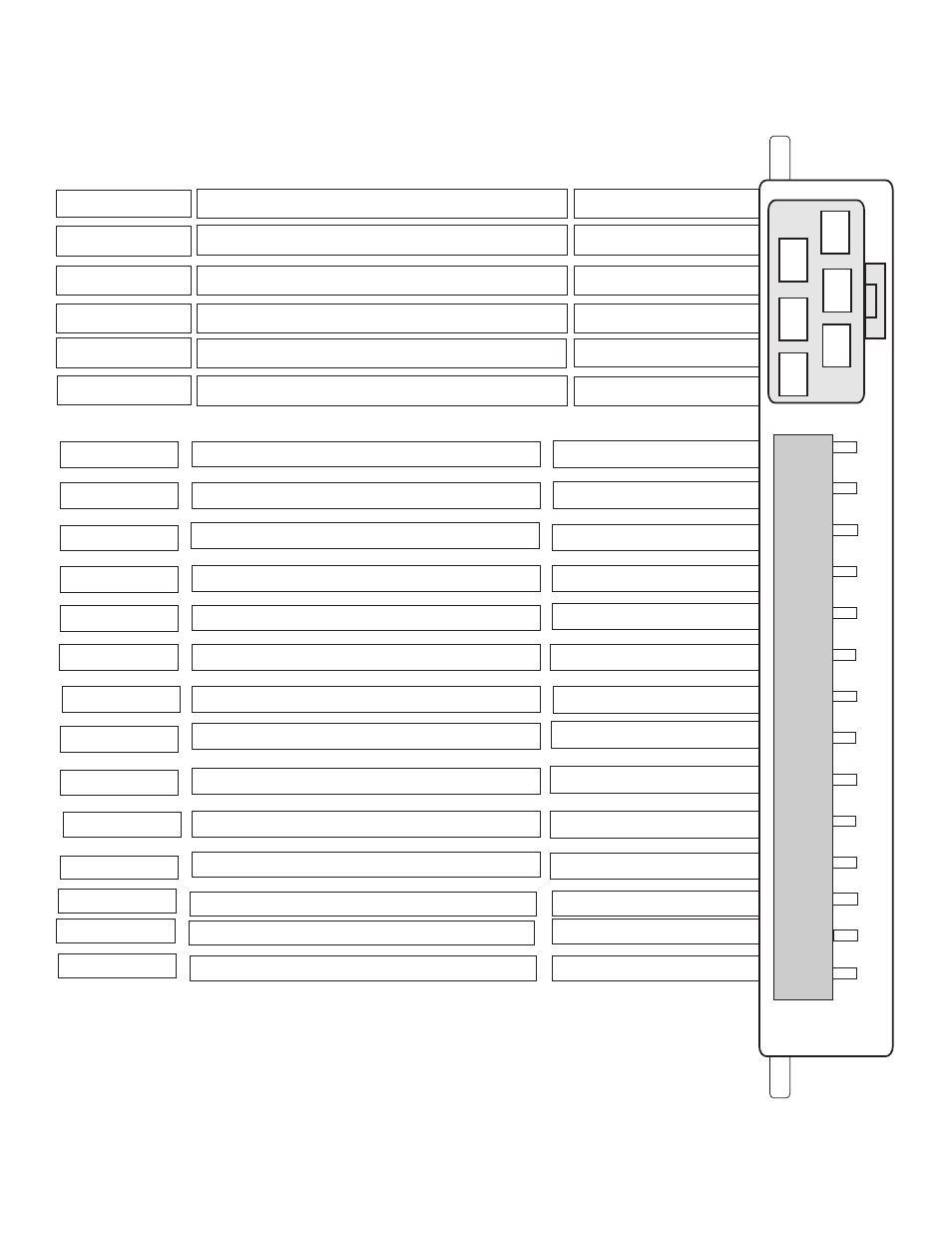
Wiring Diagram 14 pin connector
BLUE
GREEN
RED
RED
YELLOW
1
5
3
2
4
6
Starter Output
Heater/Acc Output
Power Input
Ignition Output
Selectable Output
Power Input
30amp Output
30amp Output
30amp Input
30amp Input
30amp Output
30amp Output
Factory Re-arm Output
Starter kill & Anti-Grind Output
Factory Disarm Output
Trunk Release Output
(+) Siren Output
(+)10amp Park Light Output
Negative Door Pin Input
Negative Park Brake Input
Positive Door Pin Input
Hood Pin Switch Input
System Ground Input
Brake Switch Input
Tach Detection Input
Diesel Glow Plug Input
BLUE/WHITE
YELLOW
WHITE/BLUE
BLACK
BROWN
RED/WHITE
PINK
BLUE
WHITE
GREEN/WHITE
(-)250ma Output
ORANGE
(-)250ma Output
(-)250ma Output
(-)250ma Output
Positive Output
(+ or -) Input
Negative Input
Negative Input
Positive Input
Positive Input
Positive Output
A/C Input
Negative Input
Negative Input
1
2
3
4
5
6
7
8
9
10
11
12
13
14
WHITE
BLACK/WHITE*
GREEN*
PURPLE*
* These connections are for manual transmission vehicles only!
“M” models must always be installed into manual transmission vehicles.
Manual transmission “M” modules are cased in Yellow plastics.
Note: 250ma outputs are low current and may require the installation of a relay
for the activation of optional features.
Page 6
INSTALLATION MANUAL
2WAY REMOTE STARTER/ALARM