Spektrum SPMAR6250 User Manual
Page 2
Step 4. Mounting the Antennas
To install the antennas, drill a 1/16-inch hole in the desired antenna mounting
position.
Slide the feeder antenna through the hole until the 31mm tip, and about 2mm of
coaxial, completely exit the fuselage. Using a drop of CA, glue the antenna to the
fuselage making sure that the 31mm active portion of the antenna tip is fully exposed.
Note: If the antenna is to be mounted internally (in the front of a 2.4GHz fuse), the
coaxial can be taped into position. Be sure the 31mm tip is located at least 2
inches from any significant carbon structure.
Step 5. Plugging in the Servo Leads
Plug the servo leads into the appropriate servo ports in the receiver, noting the
polarity of the servo connector. Consult your radio’s manual for specific details as to
which servo plugs into which servo port channel.
Step 6. Binding the Receiver
The AR6250 must be bound to the transmitter before it will operate. Binding is the
process of teaching the receiver the specific code of the transmitter so it will only
connect to that specific transmitter.
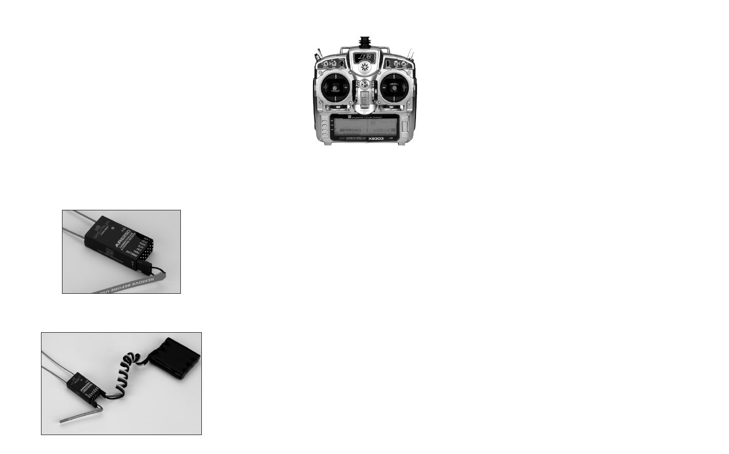
1. To bind an AR6250 to a DSM2 transmitter, insert the bind plug in the BATT/BIND
port on the receiver.
2. Power the receiver through any other port. Note that the orange LED on the
receiver should be flashing, indicating that the receiver is in bind mode and
ready to be bound to the transmitter.
3. Move the sticks and switches on the transmitter to the desired failsafe positions
for the throttle, elevator and aileron channels.
4. Follow the procedures of your specific transmitter to enter Bind Mode; the
system will connect within a few seconds. Once connected, the orange LED on
the receiver will go solid indicating the system is connected.
5. Remove the bind plug from the BATT/BIND port on the receiver before you
power off the transmitter and store it in a convenient place.
IMPORTANT: Remove the bind plug to prevent the system from entering bind
mode the next time the power is turned on.
Step 7. Radio Setup and Programming
Following the instructions in your radio manual, program your airplane.
Step 8. Rebinding the Receiver
After you’ve programmed your model, it’s important to rebind the system so the true
failsafe control surface positions are set.
Step 9. Ground Range Testing and Verification Red LED
Advanced Range Testing
In airplanes that have significant carbon fiber construction, it is imperative to first
do an advanced ground range check. This ground range check will confirm that
the receiver is operating optimally and that the antennas are properly mounted in a
position that will give positive RF coverage in all attitudes. This advanced range check
allows the RF performance of the receiver and the positions of each antenna to be
verified and to optimize the locations of the antennas.
Advanced Range Test
1. Turn on the system (Tx and Rx).
2. Have a helper hold your aircraft while observing the red LED (labeled with H)
located on the receiver.
3. Standing 30 paces away from the model, face the model with the transmitter in
your normal flying position and put your transmitter into range test mode. This
causes reduced power output from the transmitter.
4. Have your helper position the model covering all orientations (nose up, nose
down, nose toward the Tx, nose away from the Tx, etc.) while watching the red
LED, noting any correlation between the aircraft’s orientation and when holds
occur. Do this for one minute. The timer on the transmitter can be used here.
5. After one minute, release the range test button. A successful installation will
yield the following: no holds, no flashing red LED.
If any holds occur redo the test, noting the orientation of the aircraft when the holds
occur. This will allow you to change and optimize the antenna position(s) to a better
location.
Step 10. Short Test Flight Verification with Hold Indicator
When the system tests successfully, it’s time for a short near test flight. This first flight
should be close (in less than 200 feet) and about five minutes or less. After the flight,
land near yourself and check that no holds occurred. A successful flight will result in
0 holds. Extend the flight distance and times, checking the Hold data after every flight
until you are confident with the results.
IMPORTANT: Y-Harnesses and Servo Extensions
When using Y-harness or servo extensions, it’s important to use standard non-
amplified Y-harnesses and servo extensions as they can/will cause the servos to
operate erratically or not function at all. Amplified Y-harnesses were developed several
years ago to boost the signal for some older PCM systems and should not be used
with Spektrum equipment. Note that when converting an existing model to Spektrum,
be certain that all amplified Y-harnesses and/or servo extensions are replaced with
conventional non-amplified versions.
Preset Failsafe
The AR6250 features preset failsafe only on throttle, aileron and elevator channels.
Preset failsafe is ideal for sailplanes, allowing the aircraft to automatically
dethermalize if the signal is lost. With preset failsafe, the throttle, aileron and elevator
channels go to their preset failsafe positions if the signal is lost, preventing a flyaway.
Receiver Power Only
• When the receiver only is turned on (no transmitter signal is present), all
channels have no output signal, to avoid overdriving the servos and linkages.
Note: Some analog servos may drift slightly during power-up even though no
signal is present. This is normal.
After Connection
• When the transmitter is turned on and after the receiver connects to the
transmitter, normal control of all channels occurs.
• After the system makes a connection, if loss of signal occurs Preset Failsafe
drives the throttle, aileron and elevator servos to their preset failsafe position set
during binding.
Receiver Power System Requirements
Inadequate power systems that are unable to provide the necessary minimum voltage
to the receiver during flight have become the number one cause of in-flight failures.
Some of the power system components that affect the ability to properly deliver
adequate power include:
• Receiver battery pack (number of cells, capacity, cell type, state of charge)
• The switch harness, battery leads, servo leads, regulators, etc.