Spektrum SPMAR6250 User Manual
Spektrum ar6250 user guide
Receiver Installation
Airplanes with significant carbon fiber construction can create an RF shielding effect,
reducing range. The AR6250 is designed to overcome these critical RF issues in
carbon airplanes by outfitting the aircraft with two external antennas at specific points
that will ensure secure RF coverage from all angles of the aircraft.
Feeder Antennas
The AR6250 incorporates two feeder antennas, which are designed to be easily
mounted through the fuselage in carbon airplanes. The receiver has two 4-inch feeder
antennas. Each feeder antenna includes a coaxial portion (which can be thought of as
an extension) and an exposed 31mm tip antenna. The last 31mm is the active portion
of the antenna.
31mm
70 mm
Red LED Hold Indicator
The AR6250 features a red LED (labeled with H) that indicates the number of holds
that have occurred since the receiver was last powered on. The LED will flash the
number of holds then pause (e.g., flash, flash, flash, pause, flash, flash, flash, pause
indicates three holds occurred since the receiver was last turned on). Note that
holds are reset to zero when the receiver is turned off. During the first flights of a
new airplane, it’s recommended to check the red LED hold indicator. If it’s flashing,
it’s important to optimize the installation (move or reposition antennas) until no
hold occurs. On later flights, the LED Hold Indicator can be used to confirm RF link
performance.
Step 1. Identifying the Type of Carbon Aircraft
While some Hand Launch Gliders and F5D airplanes are full carbon construction,
many only use carbon in areas that require extra strength. Some of the latest
aircraft are constructed with 2.4GHz friendly fuselages, meaning that the forward
section of the fuselage is constructed from non-conductive materials like fiberglass
and Kevlar that don’t affect RF. The first step in a proper installation is identifying the
type of fuselage.
A- Full Carbon
All components of the airplane including the entire fuselage, the wing and tail are
constructed of carbon fiber or have a carbon fiber weave throughout the aircraft.
Spektrum AR6250 User Guide
Spektrum’s AR6250 6-channel full range receiver is designed for installations
in compact airplanes constructed of carbon fiber. Carbon fiber can create an RF
shielding effect that can significantly reduce radio range when using conventional
receivers and antennas. The AR6250 features an antenna design that overcomes RF
issues in these critical environments.
Compatibility
The AR6250 receiver features DSM2
™
technology and is compatible with all
Spektrum
™
and JR
®
aircraft radios that support DSM2 technology including:
JR12X
JRX9303
Spektrum DX7
Spektrum DX6i
Spektrum DX5e
Spektrum Module Systems
Note: The AR6250 receiver is not compatible with the Spektrum DX6 parkflyer
transmitter.
Features
• 6-channel receiver optimized for carbon fiber fuselage installations
• Compact endpin design is ideal for F5D and hand launch sailplanes with small
cross sections
• Offers superior RF coverage with through-the-fuselage feeder antennas
• Includes one internal receiver with two 4-inch (101mm) feeder antennas
• Red LED indicates number of holds
• Preset failsafe system on throttle aileron and elevator optimized for sailplane and
F5D applications
• QuickConnect
™
with Brownout Detection
Applications
Compact airplanes with carbon structure including:
• Carbon/ Composite F5D electrics
• Carbon hand launch and DLH gliders
• Carbon Hot-liners
• Compact aircraft with significant conductive materials (carbon, aluminum or
other metals) that could weaken the signal
Specifications
Type: DSM2 Full Range receiver for carbon aircraft
Channels: 6
Modulation: DSM2
Dimensions: 35mm x 18mm x 10mm
Weight: 4 grams
Voltage Range: 3.5 to 9.6
Resolution: 1024
Compatibility: All DSM2 aircraft transmitters
B- 2.4GHz Friendly Fuselage
The section forward of the wing is constructed of non-conductive materials like
fiberglass, Kevlar, etc. but the wing and possibly the tail section have carbon or
carbon weave construction.
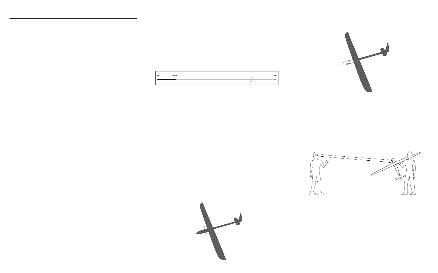
Step 2. Determining Antenna Mounting Positions
After determining which type of aircraft from the list above, use the above
illustrations as a guideline as to where the feeder antennas should be mounted. Note
that full carbon aircraft requires externally mounted antennas while the 2.4GHz-
friendly fuselage can have the antennas mounted internally. The goal is to mount the
antennas in a location so that at least one will always be in the RF visual line of sight
of the transmitter (e.g. not blocked by carbon fiber structures) in all attitudes. This
can easily be visualized by having a helper stand about 20 feet away and rotate the
airplane in all attitudes confirming that in all positions there is a direct line between
you and at least one receiver antenna that isn’t blocked by carbon fiber structure.
Step 3. Installing the Receivers
Install the receiver in the normal position recommended by the airplane’s
manufacturer. Double-sided tape or foam can be used to secure the main
receiver in place.
External Antennas
Internal Antennas
Full Carbon
2.4GHz Friendly