Allied Telesis AT-A24/SX, LX User Manual
Page 17
1000Base Expansion Module Quick Install Guide
7
5.
Secure the expansion module to the switch by tightening the captive
screws.
6.
Apply power to the switch by re-attaching the power cord to the switch.
Verify that the Power LED lights green.
7.
Remove the dust cover from the port(s) on the expansion module and
connect the data cable(s). See Table 2 for cable type and maximum length.
Note
The AT-A14 module does not come with a dust cover.
8.
Verify the LEDs on the expansion module’s front panel by referring to
Table 3.
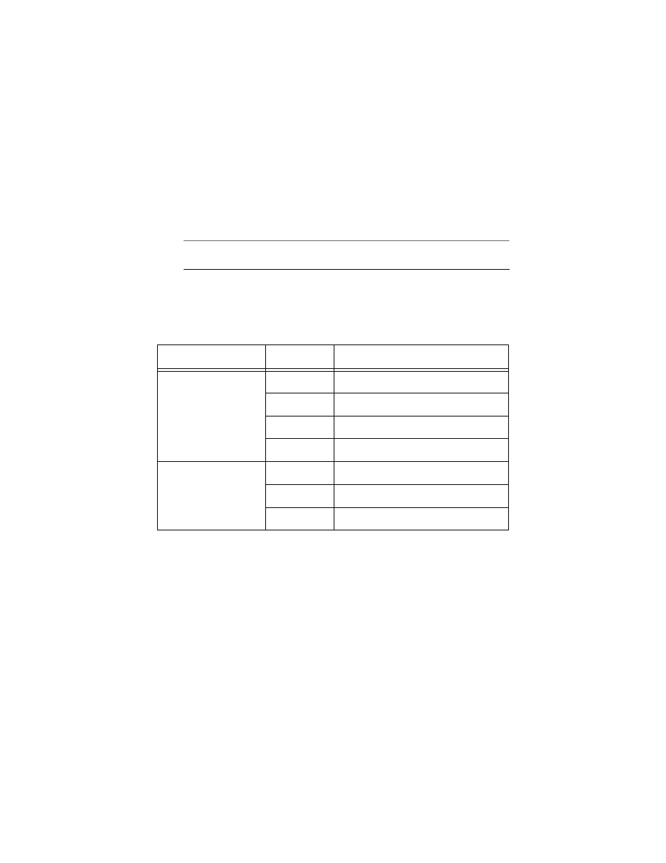
Table 3 Expansion Module LEDs
The expansion module is now ready for use.
LED
State
Description
ACTIVITY/LINK
Solid Green
Indicates a 1000 Mbps link.
Flashing Green
Indicates 1000 Mbps activity.
Solid Amber
Indicates a 100 Mbps link (AT-A14 only).
Flashing Amber Indicates 100 Mbps activity (AT-A14 only).
FULL DUP/HALF DUP/COL Solid Green
The port is operating at full-duplex.
Solid Amber
The port is operating at half-duplex.
Flashing Amber Collisions are occurring on the line.