Allied Telesis AT-FS706E FC User Manual
Page 12
2
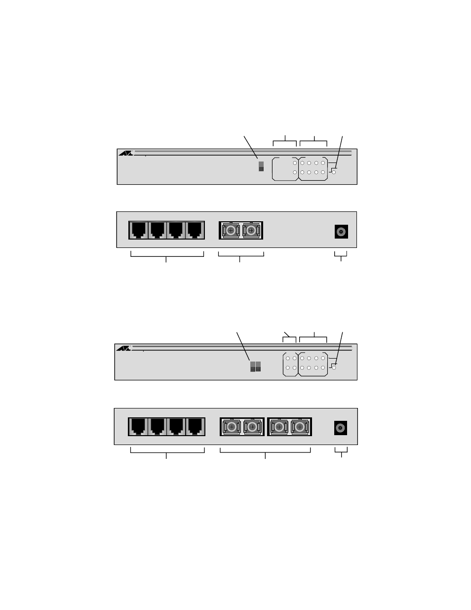
Figure 1 and Figure 2 illustrate the front and rear panels of the AT-FS705E
FC Series and AT-FS706E FC Series Ethernet switches, respectively.
Figure 1 Front and Rear Panels of the AT-FS705EFC (Model AT-FS705EFC/SC)
Figure 2 Front and Rear Panels of the AT-FS706EFC (Model AT-FS706E FC/SC)
10Base-T/100Base-TX
Ports
100Base-FX
Fiber Optic Port
DC Power
Connector
Power
LED
Twisted Pair
Port LEDs
Fiber Optic
Port LEDS
Duplex Mode Switch
Fiber Optic Port
LNK/ACT
1
2
3
4
5
PWR
10BASE-T / 100BASE-TX 4 PORT ETHERNET SWITCH WITH 100FX UPLINK
100M
LNK/ACT
FD
100FX
10/100TX
5
100FX
DUPLEX
HALF
FULL
AT-FS705E
Telesyn
Allied
FC/SC
1 2 3 4
RX
TX
5
DC In
3.3V
LNK/ACTY
1
2
3
4
5
PWR
10BASE-T / 100BASE-TX 4 PORT ETHERNET SWITCH WITH 100FX UPLINKS
100M
LNK/ACTY
FD
100FX
10/100TX
1 2 3 4
RX
TX
5
DC In
3.3V
AT-FS706E
Telesyn
Allied
FC/SC
RX
TX
6
6
5
HALF
FULL
6
100FX
DUPLEX
10Base-T/100Base-TX
Ports
Fiber Optic Ports
Connector
DC Power
100Base-FX
LED
Port LEDs
Port LEDS
Duplex Mode Switches
Power
Twisted Pair
Fiber Optic
Fiber Optic Port