Table 3: led states and recommended action (con, Checking led status, Troubleshooting 14 – Allied Telesis FORMULA 8200 User Manual
Page 18: Activity collision link diag
Troubleshooting
14
Checking LED Status
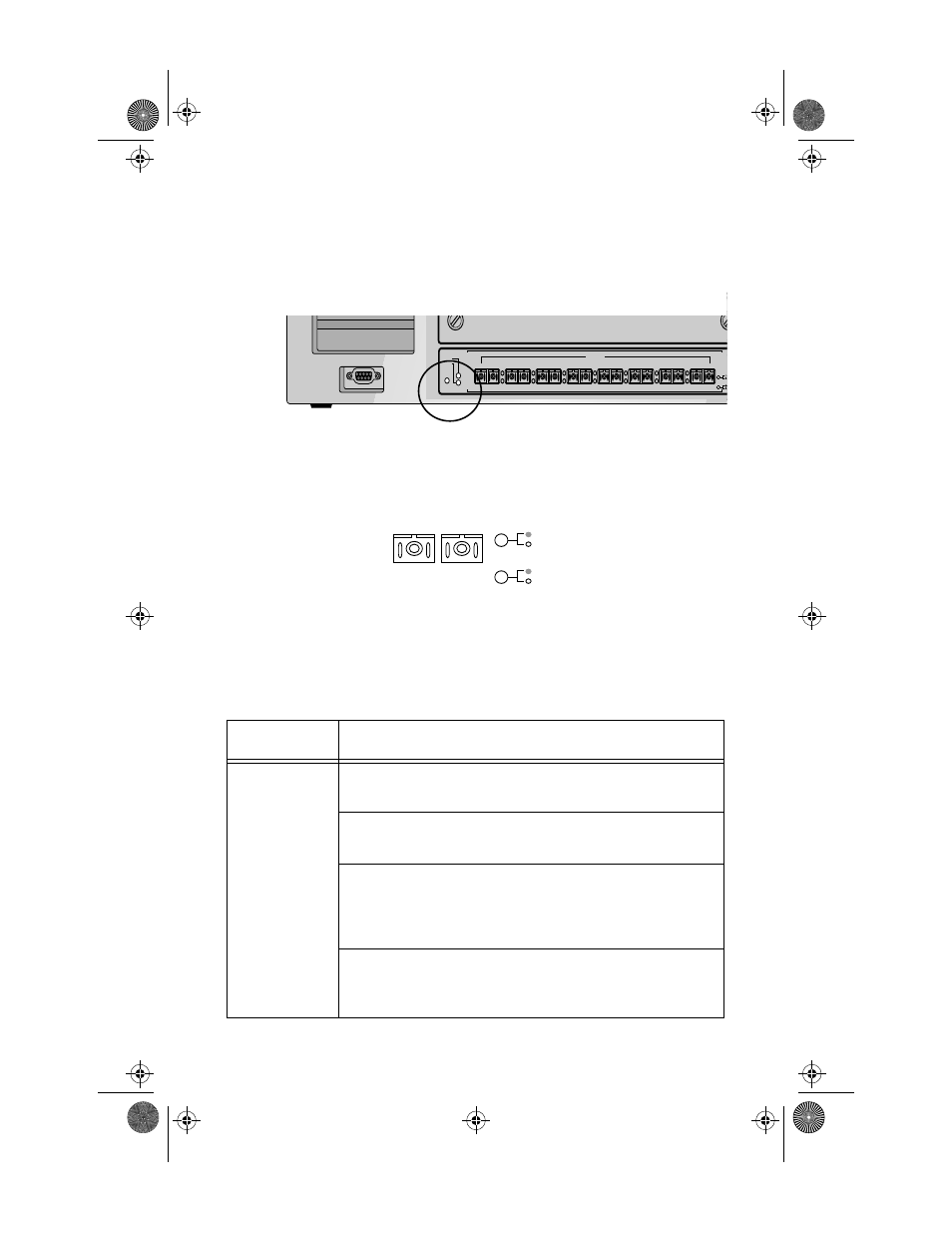
The switch has system LEDs (Status and Power), located on the front panel,
that indicate the switch’s overall operational status. For the location of these
LEDs, see the encircled area in Figure 9.
Figure 9: Switch System LEDs
Additionally, each FX port has a set of LEDs to the right. For a closeup view of
the FX LEDs, see Figure 10.
Figure 10: FX Port LEDs
Table 3 describes how these LEDs report on the switch and ports’ status, and
what you need to do in case of a problem.
Table 3: LED States and Recommended Action
LED
Description and Action Required
Status
Flashing green means the switch’s system-wide operations are
normal.
Solid green means the switch software is locked up and you
probably cannot log in. Reboot the switch.
Flashing amber means the switch is completing a DRAM test
during a power on self test (POST); otherwise, there may be
problems. Reboot. If the LED state does not change, contact Allied
Telesyn’s Technical Support.
Solid amber means the switch is still functioning, but with
problems. Try to determine the cause of the problem without
rebooting the switch. If all else fails, reboot.
10/100BASE-T NETWORK PORTS
9
10
11
12
10/100BASE-T NETWORK PORTS
13
14
15
16
10/100BASE-T NETWORK PORTS
1
2
3
4
10/100BASE-T NETWORK PORTS
5
6
7
8
STATUS
POWER
RESET
GREEN - LINK
YELLOW - DIAG
GREEN - ACTIVITY
YELLOW - COLLISION
RS-232 TERMINAL PORT
100 BASE-FX
1
2
3
4
5
6
7
8
STATUS
POWER
RESET
A
Activity
Collision
Link
Diag
Fiber_Book Page 14 Tuesday, February 17, 1998 1:43 PM