Allied Telesis AT-8324 User Manual
Page 13
AT-8316F and AT-8324 Quick Install Guide
7
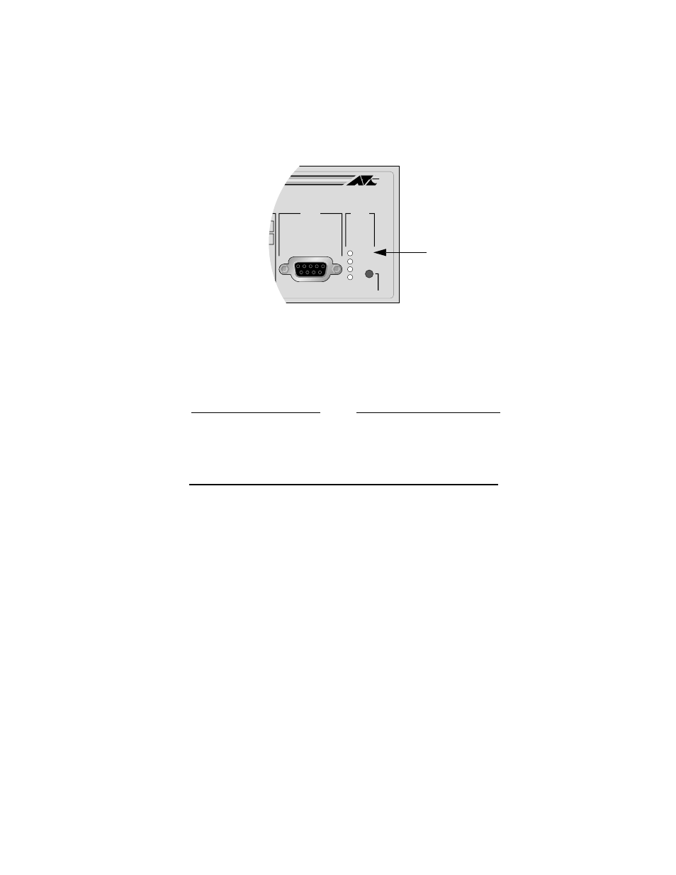
Figure 4 Fault LED
7.
If you purchased a redundant power supply (RPS) unit for the Ethernet
switch, connect the RPS unit to the R.P.S. Input connector (Figure 3) on
the rear of the switch by following the directions included with the RPS
system.
Caution
If you intend to use a redundant power supply (RPS) with the
switch, check to be sure that the cable with the RPS unit is
compatible with the RPS Input Port on the switch. The pin
assignments for the port are provided in the section “R.P.S. Input
Connector Specifications” on page 13.
8.
Connect the data cables, making sure each connection has a good valid link
and that the switch is receiving packets.
9.
Go to the procedure “Setting Up for Local Management” on page 10 to
access the Omega management software on the switch.
STATUS
RESET
FAULT
RPS
PWR
RS-232
TERMINAL PORT
L
MASTER
Fault LED