Allied Telesis AT-8324 User Manual
Page 12
Installing the Switch
6
Note
Do not set the Stack ID switch to 0. A setting of 0 is invalid.
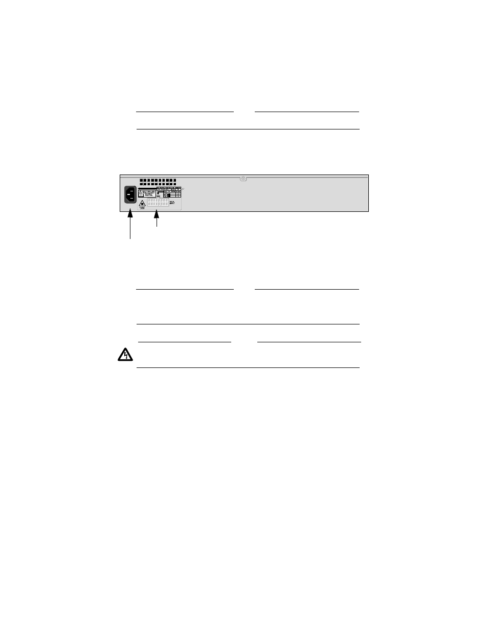
6.
Apply AC power to the switch by plugging the power cord into the AC
power connector on the back panel of the unit (shown in Figure 3) and
plugging the other end into a wall outlet.
Figure 3 AT-8316F and AT-8324 Ethernet Switch Rear Panel
Note
For instructions on powering on an AT-8316F or AT-8324 Ethernet
stack, refer to the AT-8316F/MT, AT-8316F/VF, AT-8316F/SC,
and AT-8324 Installation Guide.
Caution
The power cord is used as a disconnect device. To de-energize
equipment, disconnect the power cord.
! 10
As power is applied to the switch, the Fault LED (shown in Figure 4)
flashes as the switch runs a series of internal self-tests and configures the
hardware. Once the self-tests are finished and the system is configured,
the Fault LED will stop flashing and will remain OFF. Refer to the section
“Switch LEDs” on page 11 for information on all of the system and port
LEDs.
AC Power Connector
R.P.S. Input Connector