Phy address, Auto-detection, Cabling – Allied Telesis AT-MX400T4 User Manual
Page 2: Automatic polarity correction, Figure 1: link segment wiring, Warranty, Electrical safety and installation requirements, Radiated energy, U.s. federal communications, Note: this equipment has been tested and found to
PHY Address
The PHY section of the micro transceiver is always set to an address (typically 1).
This address is used locally by the DTE to differentiate multiple PHYs connected to a
single MII. Addresses are selected using the Physical Address DIP switch on the front
of the transceiver. The address range is 0-1 decimal; the default setting as shipped is
address
1.
NOTE
When the address is set to 0, the transceiver is in Isolation Mode. In Isolation
Mode, the transceiver responds only to MDIO and MDC signals and ignores all
other MII signals.
Auto-Detection
The AT-MX400T4 supports auto-detection. If the other end supports 100Base-T4, the
AT-MX400T4 will auto switch to 100mb/s at half duplex. If the other end supports
10Base-T the AT-MX400T4 will auto switch to 10mb/s at half duplex.
Cabling
The AT-MX400T4 uses RJ45 connectors and 4-pair wire of category 3, 4, or 5
unshielded twisted pair (UTP) or type 1 shielded twisted pair (STP). The recom-
mended maximum cable length is 100 meters.
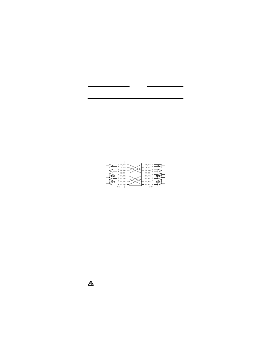
Automatic polarity correction.
The transceiver should be connected with a
straight-through cable to a hub or a crossover cable to another PHY. See Figure 1 for
standard wiring to a hub. If the polarity is inverted, the MX400T4 automatically cor-
rects polarity.
Figure 1:
Link Segment Wiring
Warranty
The AT-MX400T4 transceiver has a lifetime warranty.
Electrical Safety and Installation Requirements
RADIATED ENERGY
U.S. Federal Communications
Note: This equipment has been tested and found to comply with the limits for a Class A digital device
pursuant to Part 15 of FCC Rules. These limits are designed to provide reasonable protection against
harmful interference when the equipment is operated in a commercial environment. This equipment
generates, uses, and can radiate radio frequency energy and, if not installed and used in accordance with
this instruction manual, may cause harmful interference to radio communications. Operation of this
equipment in a residential area is likely to cause harmful interference in which case the user will be
required to correct the interference at his own expense.
Note: Modifications or changes not expressly approved of by the manufacturer or the FCC, can void
your right to operate this equipment.
Canadian Department of Communications
This Class A digital apparatus meets all requirements of the Canadian Interference-Causing Equipment
Regulations.
Cet appareil numérique de la classe A respecte toutes les exigences du Règlement sur le matériel
brouilleur du Canada.
STANDARDS:
This product meets the following standards
RFI EmissionEN55022 Class A
WARNING:
In a domestic environment this product may cause radio interference in which case the
user may be required to take adequate measures.
Immunity EN50082-1
Electrical Safety EN60950, UL1950, CSA 950
SAFETY
LIGHTNING DANGER
DANGER: DO NOT WORK on equipment or CABLES during periods of LIGHTNING ACTIVITY.
Operating temperature
This product is designed for a maximum ambient temperature of 40 degrees C.
TX_D1+
TX_D1-
RX_D2+
RX_D2-
B1_D3+
B1_D3-
B1_D4+
B1_D4-
TX_D1+
TX_D1-
RX_D2+
RX_D2-
B1_D3+
B1_D3-
B1_D4+
B1_D4-
1
2
3
6
4
5
7
8
1
2
3
6
4
5
7
8
PHY
PHY