Allied Telesis AT-GS908 User Manual
Page 29
AT-GS908 Gigabit Ethernet Switch Installation Guide
19
5. Verify that the PWR LED is green. If the LED is OFF, refer to
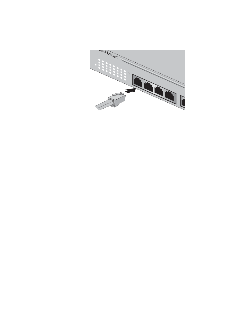
6. Connect the twisted pair data cables to the RJ-45 ports on the switch,
as shown in Figure 7.
Figure 7 Connecting the Twisted Pair Data Cables
When connecting a twisted pair cable to a port, observe the
following guidelines:
An RJ-45 connector should fit snugly into the port on the switch.
The tab on the connector should lock the connector into place.
The ports on the switch are auto-MDI/MDI-X when operating at 10
or 100 Mbps. You can use either a straight-through or crossover
twisted pair cable to connect any type of network device to a port
on the switch when operating at either 10 or 100 Mbps.
For ports operating at 1000 Mbps, use a straight-through cable.
The network should not contain data loops, which can adversely
affect network performance. A data loop exists when two or more
network devices can communicate with each other over more
than one data path.
7. Power on the end-nodes.
8. Depending on your configuration, check that the 10 or 100 LED for
each port connected is green. ( If both LEDs are green, the unit is
opearing at 1000 Mbps.) If the LEDs are OFF, refer to
Troubleshooting on page 23.
The switch is ready for network operations.
GS
908
GB
100
/1000
Base
-T G
iga
bit E
the
rne
t S
witch
with
G
BIC
Up
links
10
100
AC
T
FDX
PWR
2
3
4
1
1000
1
2
3
4
5
6
7
8