At-fs202, At-fs202sc/fs4, Description 2 – Allied Telesis AT-FS202SC/FS4 User Manual
Page 10: 12 v d c, Dip switches dc receptacle, Port
Description
2
Figure 1 illustrates the front panel of an AT-FS20x Series switch.
Figure 1 AT-FS20x Series Front Panel (AT-FS202 Model)
Figure 2 illustrates a front panel of an AT-FS202SC/FSx Series switch.
Figure 2 AT-FS202SC/FSx Series Front Panel (AT-FS202SC/FS4 Model)
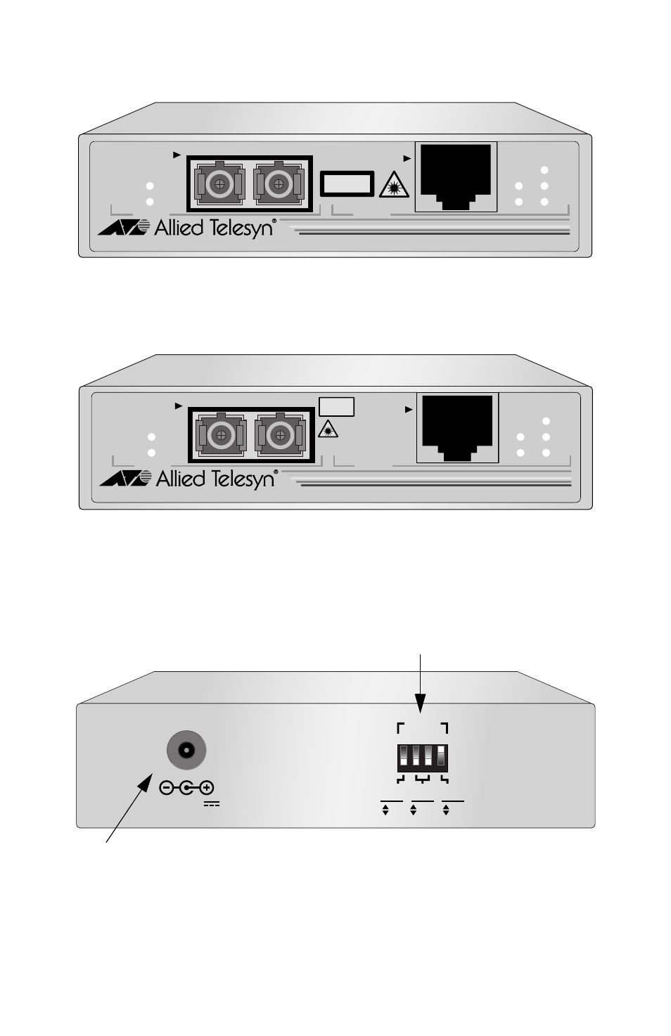
The back panel of the AT-FS20x and AT-FS202SC/FSx Series switches
features a power adapter connector and DIP switches for manually
configuring the ports. Figure 3 illustrates the back panel.
Figure 3 Back Panel of the AT-FS20x and AT-FS202SC/FSx Series Switches
10Base-T/
100Base-TX
AT-FS202
FAST ETHERNET SWITCH IEEE 802.3 / 802.3U
LNK/
ACT
FD/
COL
PWR
AUTO
NEG
100M
LNK/
ACT
FD/COL
PORT 2
100Base-FX
TX
RX
PORT 1
CLASS 1
LASER PRODUCT
AT-FS202SC/FS4
FAST ETHERNET SWITCH IEEE 802.3 / 802.3U
LNK/
ACT
FD/
COL
PWR
AUTO
NEG
100M
LNK/
ACT
FD/COL
PORT 2
100Base-FX
TX
RX
PORT 1
10Base-T/
100Base-TX
CLASS 1
LASER PRODUCT
DO NOT STARE
INTO BEAM
SINGLE MODE
12 V D C
2
1
3
4
1
2
2 2
PORT
10
100
HALF
FULL
OFF
ON
DUPLEX
MODE
AUTO
NEG
SPEED
(Mbps)
DIP Switches
DC Receptacle