Technical specifications, Electrical safety and emission statement, Physical and environmental – Allied Telesis AT-CVFAN User Manual
Page 2: Electrical ratings
Caution
Be sure to observe all standard electrostatic discharge (ESD)
precautions, such as wearing an antistatic wrist strap, to avoid
damaging the device. A fan module can be damaged by static
electricity.
Note
You must use the original shipping material if you need to return the fan
module to Allied Telesis.
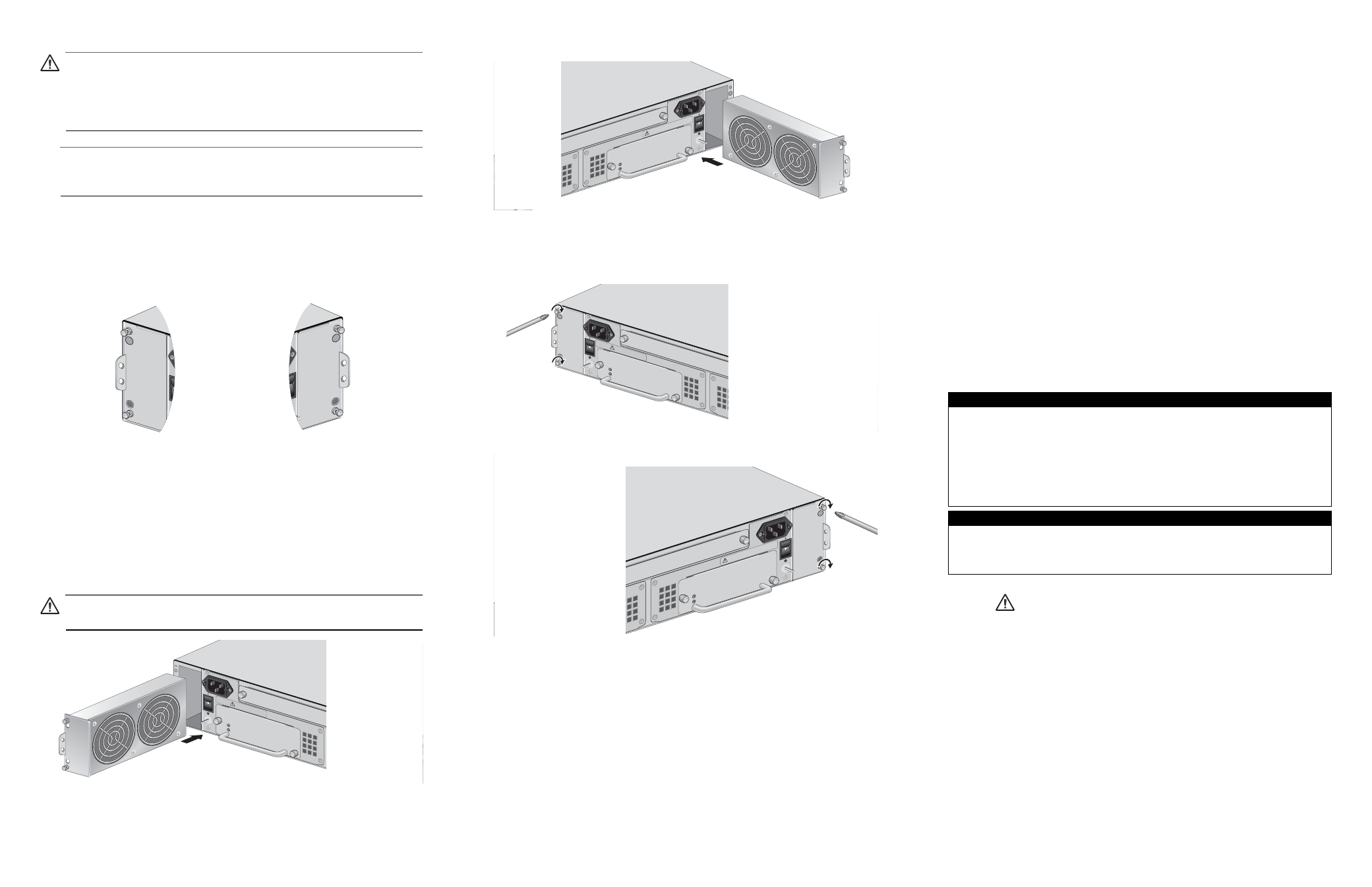
5. Carefully remove the fan module from the chassis.
6. Make sure the handles on the fan modules are aligned to the side edges
of the chassis. For example, the handle on the fan module inserting into
Fan Slot A should be on the left and the handle on the module inserting
into Fan Slot B should be on the right, as shown in Figure 6.
Figure 5. Aligning the AT-CVFAN Modules to the AT-CV5000 Chassis
7. Align the new fan module with the bottom alignment guide, located inside
the fan slot.
8. Slide the new fan module into the fan slot, as shown in Figure 6 or
Figure 7, until the front of the fan module is flush with the front of the
chassis.
Caution
Avoid touching the fan blades.
Figure 6. Inserting an AT-CVFAN Module into the Fan Slot A
291
AT-CVFAN
A
292
AT-CVFAN
B
AT-CVFAN module in
Fan Slot A
AT-CVFAN module in
Fan Slot B
Handles
on Left
Handles
on Right
AT-CV5
PWRAC
POWE
R
FAULT
AT-PWR
14
A
B
POWE
R
FAULT
A
A
T
-CVF
AN
202
100-2
40VAC
~
WARN
ING
This unit m
ight ha
ve m
ore than one p
ower input.
To
reduce the
risk of e
lectric shoc
k, disconn
ect all po
wer
inputs bef
ore ser
vicing un
it.
Figure 7. Inserting an AT-CVFAN Module into the Fan Slot B
9. Tighten the two captive screws on the fan module, as shown in Figure 8 or
Figure 8. Tightening the Screws on the AT-CVFAN Module in Fan Slot A
Figure 9. Tightening the Screws on the AT-CVFAN Module in Fan Slot B
You have completed the fan replacement procedure.
To power on the chassis, proceed to the procedure described in the
“Powering On an AC Powered Chassis” section in the AT-CV5000 Chassis
Installation Guide.
When the connection is established, the fan LED (FAN-A or FAN-B) on the
LED interface card should show green. If the LED is OFF, refer to the
“Troubleshooting” section in the AT-CV5000 Chassis Installation Guide.
AT-PWR14
AT-CV5P
WRAC
B
B
POW
ER
FAUL
T
A
T
-CVF
AN
203
100-240V
AC
~
WARNING
This unit m
ight ha
ve more th
an one p
ower input.
To
reduce the
risk of electric
shoc
k, disconnec
t all
power
inputs bef
ore s
ervicing uni
t.
AT-CV5PWRAC
POWE
R
FAULT
AT-PWR1
4
A
B
100
-240V
AC
~
AT-CV5F
A
B
POW
ER
FAULT
AT-CVFAN
A
206
100-2
40VAC
~
WARN
ING
This unit m
ight ha
ve m
ore t
han one
powe
r input.
To
reduce the
risk of el
ectric sh
ock, disco
nnect all po
wer
inputs be
fore ser
vicing
unit.
AT-PWR14
AT-CV5P
WRAC
A
B
100-240
VAC
~
POW
ER
FAULT
AT-CVFAN
B
20
100-240
VAC
~
WA
RNIN
G
This uni
t might
have more
than one po
wer input.
To
reduce the risk
of electric shoc
k, disconn
ect all po
wer
inputs bef
ore ser
vicing unit.
Technical Specifications
Physical and Environmental
Dimensions (H x W x L)
2.7 cm x 8.3 cm x 18.8 cm
1.080 in x 3.287 in x 7.395 in
Operating Temperature
0° C to 40° C (32° F to 104° F)
Storage Temperature
-25° C to 70° C (-13° F to 158° F)
Operating Relative Humidity
5% to 90% RH (non-condensing)
Storage Relative Humidity
5% to 95% RH (non-condensing)
Operating Altitude Range
Up to 3,048 m (10,000 ft)
Electrical Ratings
Rated Voltage
12V DC
Operation Voltage
7.0V DC - 13.2V DC
Input Current
0.23 A (maximum 0.34 A)
Input Power
2.76 W (maximum 4.08 W)
Electrical Safety and Emission Statement
Standards: This product meets the following standards when installed in compliant host equipment.
Emission
FCC Class A, EN55022 Class A, VCCI Class A, C-TICK, CE
WARNING:
In a domestic environment this product may cause radio interference in which case the
user may be required to take adequate measures.
Immunity
EN55024
Electrical Safety
UL60950 (UL/
c
UL), EN60950 (TUV), CSA22.2 No. 950
Copyright
2006 Allied Telesis, Inc. All rights reserved.
No part of this publication may be reproduced without prior written permission from Allied Telesis Inc.
U.S. Federal Communications Commission
RADIATED ENERGY
Note: This equipment has been tested and found to comply with the limits for a Class A digital device pursuant
to Part 15 of FCC Rules. These limits are designed to provide reasonable protection against harmful
interference when the equipment is operated in a commercial environment. This equipment generates, uses,
and can radiate radio frequency energy and, if not installed and used in accordance with this instruction
manual, may cause harmful interference to radio communications. Operation of this equipment in a residential
area is likely to cause harmful interference in which case the user will be required to correct the interference at
his own expense.
Note: Modifications or changes not expressly approved of by the manufacturer or the FCC, can void your right
to operate this equipment.
Industry Canada
This Class A digital apparatus meets all requirements of the Canadian Interference-Causing Equipment
Regulations.
Cet appareil numérique de la classe A respecte toutes les exigences du Règlement sur le matériel brouilleur
du Canada.
4
5
6