Step 8, Quick install guide 5, Ac power at-rps9000 rps connector compact flash – Allied Telesis AT-9800 Series Switch User Manual
Page 5
Quick Install Guide
5
C613-04038-01 REV H
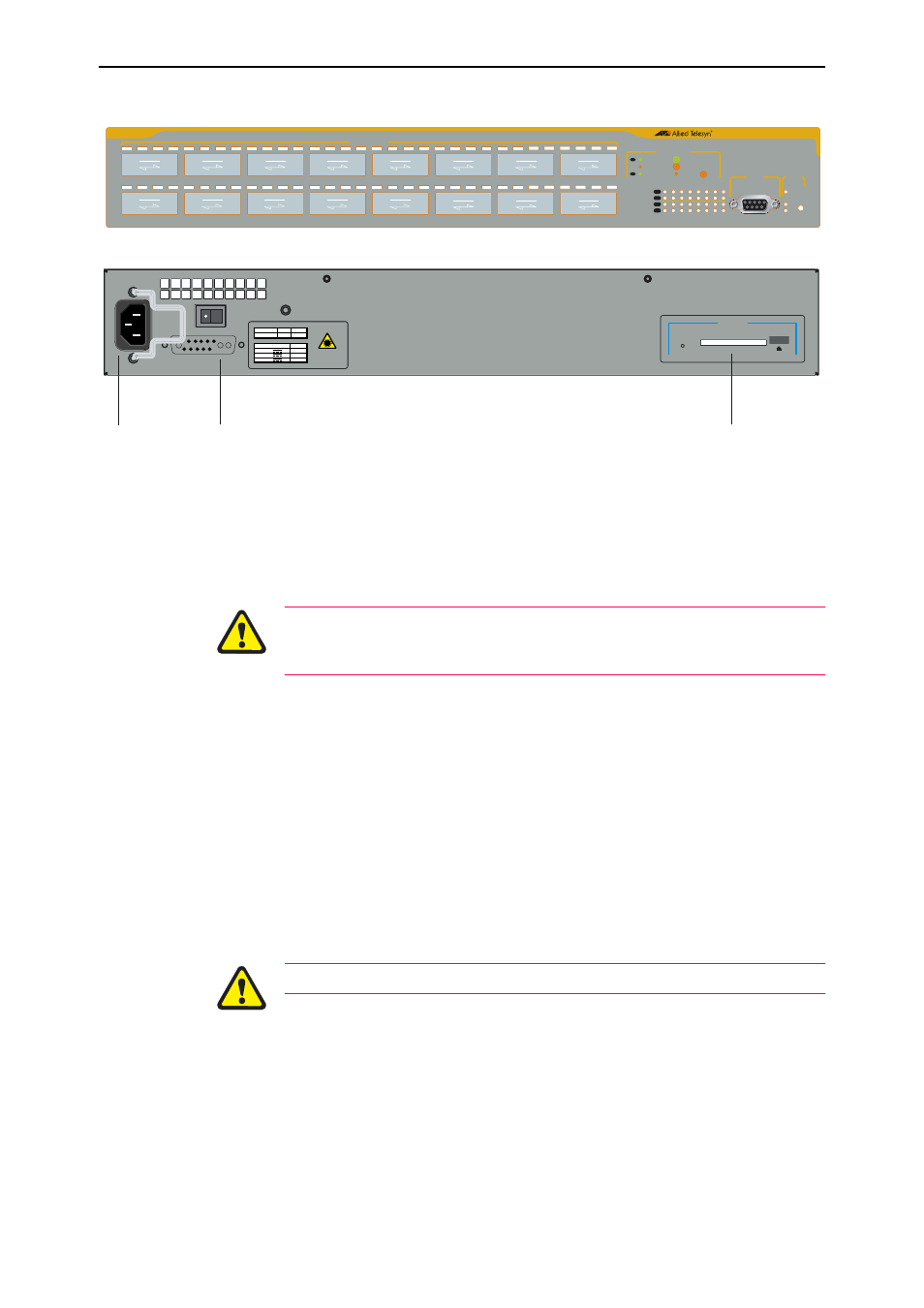
Figure 1: AT-9816GB front panel and rear panel with AC power inlet
8.
Apply DC power to the switch (for DC models)
Read the AT-9800 Series Safety and Statutory Information booklet before
connecting a DC power supply. A copy of this booklet is included with
each switch. It is also included on the Documentation and Tools CD-ROM,
or can be downloaded from
.
Only trained and qualified personnel should connect a DC power supply. Due
to exposed terminals, DC powered switches should only be installed in
Restricted Access Areas.
DC supply cable specifications (one cable is required for each PSU):
•
Number of wires (cores): 3
•
Minimum size: 2.1mm
2
(14 AWG)
•
Minimum cable rating: 600 V, 90 degrees Celsius
DC power supply specifications:
•
48V DC (40–60 VDC is acceptable)
•
Either positive grounded or negative grounded
Circuit protection:
•
Use a 10 Amp circuit breaker
Ensure the supply cable is not live.
a)
Strip the supply cable wires to expose 8mm (0.31in) of bare conductor
b)
At the switch, connect the ground wire to the ground terminal. The
terminals can be identified by the diagram on the rear panel of the
switch. Tighten the terminal to between 0.6 and 0.8Nm (0.041 to 0.055
pound force per foot).
c)
At the switch, connect the positive feed to the + (positive) terminal and
the negative feed to the - (negative) terminal. Tighten the terminal to
between 0.6 and 0.8Nm (0.041 to 0.055 pound force per foot).
CLASS 1
LASER
AC INPUT
100-240V
HZ
50/60
AMPS
5.0/2.5
RPS INPUT VDC A Max
16
16
0.5
+3.3
+5
+12
COMPACT FLASH
ACTIVITY
AC Power
AT-RPS9000 RPS Connector
Compact FLASH
STATUS
RESET
FAULT
PWR
RPS
1
9
2
10
3
11
4
12
5
13
6
14
7
15
8
16
1
2
3
4
5
6
7
8
9
10
11
12
13
14
15
16
RS-232
TERMINAL PORT
L/A
GBIC
L/A
GBIC
ASYN0
1000BASE-X GBIC
PORT ACTIVITY
L/A
LINK / FULL DUP
ACTIVITY
LINK / HALF DUP
ACTIVITY
L/A
L/A
ENABLED
DISABLED
FAULT
GBIC
L/A
L/A
GBIC
AT-9816GB V2
Layer 3 Fast Ethernet Switch