Allied Telesis CAM User Manual
Page 4
4
Content Addressable Memory (CAM)
C613-04037-01 REV E
6.
Remove the switch’s lid.
The switch may need to be removed from any rack mounting system
before its lid can be removed.
Using a posidrive screwdriver, remove the 12 screws that secure the
switch’s lid. There are 5 screws located in countersunk holes on each side
of the lid, and 2 screws at the rear.
7.
Align the CAM.
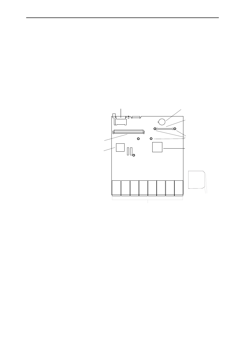
Position the CAM card over the CAM slot on the switch’s PCB. The three
support pillars located on the board should be aligned with the holes on
the CAM card, and the cards chamfers should be pointing to the switch’s
PSU (see Figure 1 on page 4).
Figure 1: AT-9800 Series CAM slot and pillar mounts.
8.
Insert the CAM extender card.
Press the CAM card firmly into place. Secure the card to the support pillars
using the supplied screws.
The CAM card is now ready to test.
CAM mounts
Switch chip
CAM slot
Battery
Compact Flash
DIMM slot
CPU
Ports
Correct CAM
orientation
Chamfers
- AT-GS908M (54 pages)
- AT-x230-10GP (80 pages)
- AT-GS950/48PS (64 pages)
- AT-GS950/10PS (386 pages)
- AT-GS950/16PS (386 pages)
- AT-GS950/48PS (386 pages)
- AT-9000 Series (258 pages)
- AT-9000 Series (1480 pages)
- IE200 Series (70 pages)
- AT-GS950/48 (378 pages)
- AT-GS950/48 (60 pages)
- AT-GS950/48 (410 pages)
- AT-GS950/8 (52 pages)
- SwitchBlade x8106 (322 pages)
- SwitchBlade x8112 (322 pages)
- SwitchBlade x8106 (240 pages)
- SwitchBlade x8112 (240 pages)
- AT-TQ Series (172 pages)
- AlliedWare Plus Operating System Version 5.4.4C (x310-26FT,x310-26FP,x310-50FT,x310-50FP) (2220 pages)
- FS970M Series (106 pages)
- 8100S Series (140 pages)
- 8100L Series (116 pages)
- x310 Series (116 pages)
- x310 Series (120 pages)
- AT-GS950/16 (44 pages)
- AT-GS950/24 (404 pages)
- AT-GS950/24 (366 pages)
- AT-GS950/16 (404 pages)
- AT-GS950/16 (364 pages)
- AT-GS950/8 (404 pages)
- AT-GS950/8 (364 pages)
- AT-GS950/8 (52 pages)
- AT-8100 Series (330 pages)
- AT-8100 Series (1962 pages)
- AT-FS970M Series (330 pages)
- AT-FS970M Series (1938 pages)
- SwitchBlade x3106 (288 pages)
- SwitchBlade x3112 (294 pages)
- SwitchBlade x3106 (260 pages)
- SwitchBlade x3112 (222 pages)
- AT-S95 CLI (AT-8000GS Series) (397 pages)
- AT-S94 CLI (AT-8000S Series) (402 pages)
- AT-IMC1000T/SFP (23 pages)
- AT-IMC1000TP/SFP (24 pages)
- AT-SBx3106WMB (44 pages)