Allied Telesis Uplink Module User Manual
Page 6
6
Uplink Module
C613-04022-01 REV H
8.
Secure the Uplink Module to the switch unit
Firmly press the Uplink Module until its connectors engage the uplink bay
connectors inside the switch unit.
Use a screwdriver to tighten the Uplink Module’s screws. Do not
over-tighten the screws.
9.
For AT-A42/GBIC uplink modules, install the GBIC
Slide the GBIC into the uplink’s GBIC slot. Press the GBIC firmly into
place.
A range of GBICs have been tested and approved for use with AT-A42 uplink modules.
Contact your authorised Allied Telesis distributor or reseller for more information, or
visit www.alliedtelesyn.com.
RX and TX terminal locations on SC fibre GBIC ports are the reverse of TX and RX
terminal locations on fixed SC fibre ports. When looking at an SC fibre GBIC from the
front, the RX terminal is on the left and the TX terminal is on the right.
10. Apply power to the switch unit
The switch’s Fault LED should flash for approximately 10 seconds as it
runs internal tests.
11. If you disconnected a redundant power supply in step 3, reconnect it
12. Check that the Power LED on the switch unit’s front panel lights green
If the LED fails to light, refer to the Troubleshooting section of the Uplink
Module Hardware Reference.
13. Connect the data cables
If fitted, remove the Uplink Module’s port dust cover, and connect the data
cable. Make sure each cable connection is secure.
14. Check the Uplink Module’s LEDs
The following tables outline the Uplink Module LEDs. Information on
Switch System and Switch Port LEDs can be found in the Troubleshooting
section of the Hardware Reference for your switch unit.
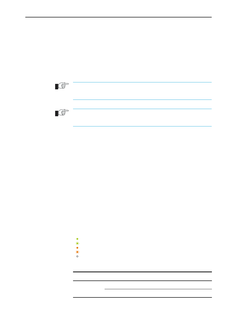
LED legend
Table 1: AT-A35/SX and AT-A35/LX LEDs.
LED
State
Function
Link
Green
The port is receiving light
Off
No link is present
LED is On and Green
LED is Flashing Green
LED is On and Amber
LED is Flashing Amber
LED is Off.