At9424t/sp switch, At-9424t/sp switch, Figure 3 – Allied Telesis AT-9448Ts/XP (Basic Layer 3) User Manual
Page 19: At-9424t/sp switch - front and back panels, Sfp transceiver slots, D/c l/a
AT-9400 Series Gigabit Ethernet Switches Installation Guide
19
AT-9424T/SP
Switch
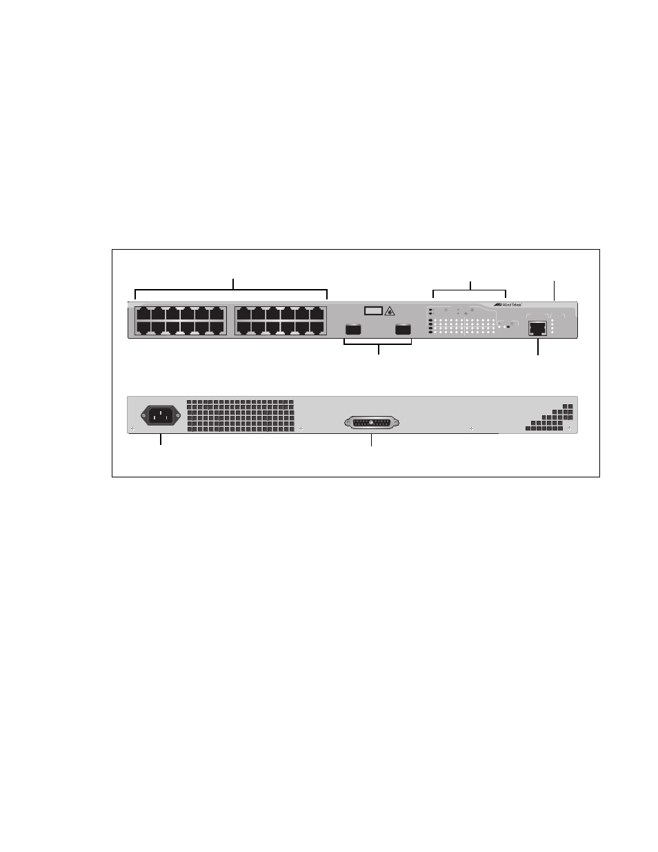
The hardware features of the AT-9424T/SP Layer 2+ Switch include:
24 10/100/1000Base-T ports
Two Gigabit Ethernet small form-factor pluggable (SFP) transceiver
slots
An RJ-45 style serial terminal port for local (out-of-band) management
Status LEDs for the ports, transceiver slots, and system
Redundant power supply connector
Figure 3 shows the front and back panels of the AT-9424T/SP Switch.
Figure 3
AT-9424T/SP Switch - Front and Back Panels
10/100/1000Base-T Ports
Port and SFP
RJ-45 Style Serial
Terminal Port
SFP Transceiver Slots
FAULT
RPS
MASTER
POWER
CLASS 1
LASER PRODUCT
STATUS
TERMINAL
PORT
1
3
5
7
9
11
2
4
6
8
10
12
13
15
17
19
21
23R
14
16
18
20
22
24R
AT-9424T/SP
Gigabit Ethernet Switch
1
3
5
7
9
11
13
15
17
19
21
23R
2
4
6
8
10
12
14
16
18
20
22
24R
23
24
L/A
D/C
D/C
L/A
D/C
L/A
1000 LINK / ACT
HDX / COL
FDX
10/100 LINK / ACT
PORT ACTIVITY
L/A
1000 LINK / ACT
SFP
SFP
24
SFP
23
AC Power
Connector
RPS Connector
Slot LEDs
System
LEDs
RPS INPUT
100-240VAC
~