Troubleshooting – Allied Telesis AT-A65 Expansion Module User Manual
Page 6
6
AT-A65 Expansion Module
613-001135 Rev A
8. Restart the switch.
Until the switch is restarted, the output of the show system and show switch
port commands cannot reflect the newly inserted module or SFP.
When you restart the switch, the Fault LED may flash for approximately 10
seconds as it runs internal tests.
9. Check that the PWR LED on the switch’s front panel lights green.
If the LED fails to light, refer to
.
10. Connect the twisted pair or fiber optic data cable.
If fitted, remove the expansion module’s port dust cover, and connect the data
cable. Make sure the cable connection is secure.
11. Check the expansion module’s LEDs.
“AT-A65 Expansion Module LEDs” on page 7
to check the
module’s LEDs. Information on switch system and switch port LEDs can be
found in the Troubleshooting section of the Hardware Reference for your
switch.
Troubleshooting
This section provides information on how to detect and resolve the most common
problems that can cause expansion modules to malfunction. Other sources of
troubleshooting information are:
■
www.alliedtelesis.com.
■
The Software Reference for your switch unit.
Performing the following tasks will eliminate the most common faults:
■
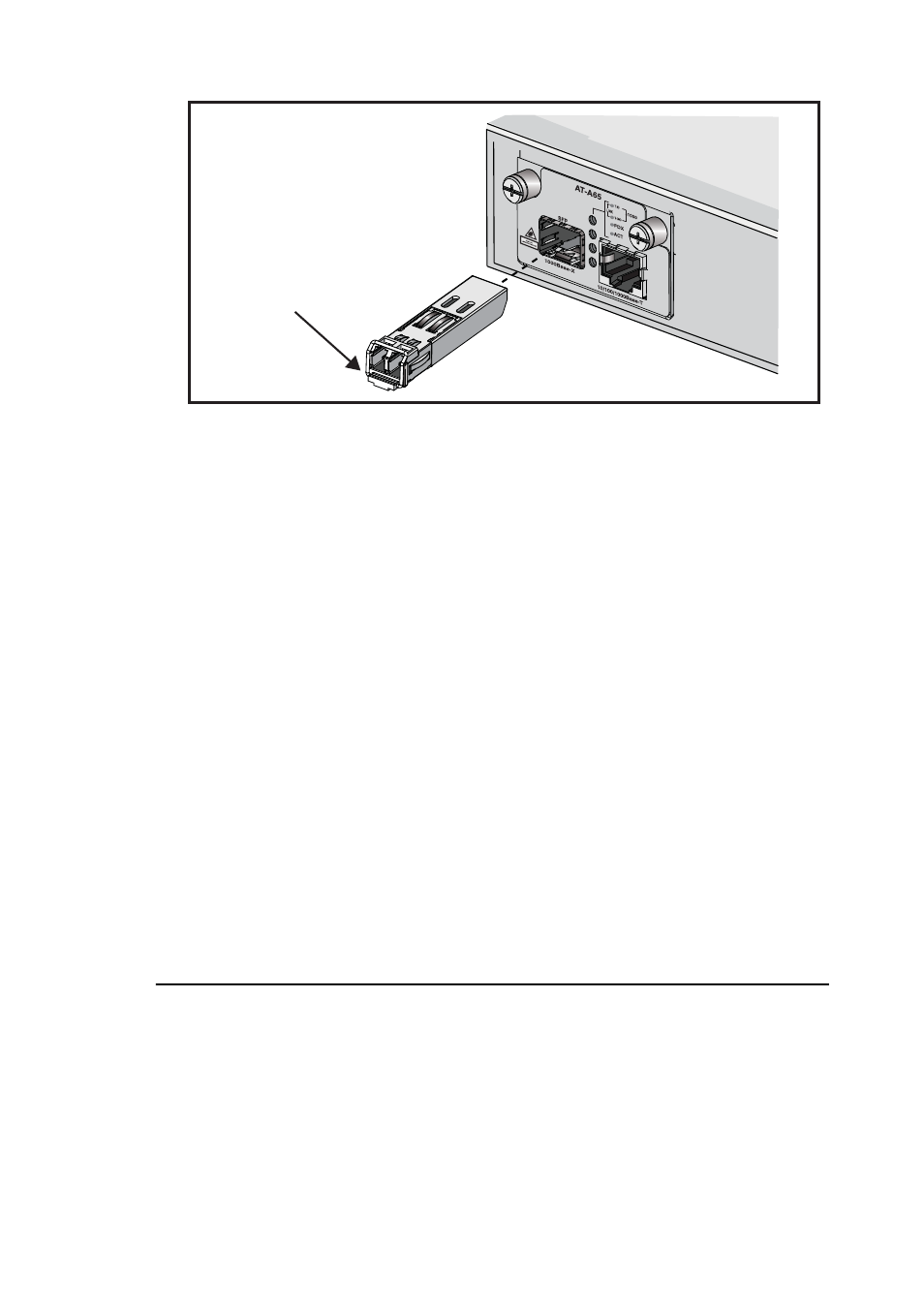
Check that the AT-A65 is correctly installed.
release lever
hinge
module_sfp.eps