Card guide – Allied Telesis AT-A65 Expansion Module User Manual
Page 5
Installation and Safety Guide
5
613-001135 Rev A
4. Prepare the expansion module.
In an antistatic environment, remove the module from its packing material. Be
sure to observe ESD precautions.
Warning Do not attempt to install an expansion module without observing
correct antistatic procedures. Failure to do so may damage the switch or
expansion module. If you are unsure what the correct procedures are, contact
your authorised Allied Telesis distributor or reseller.
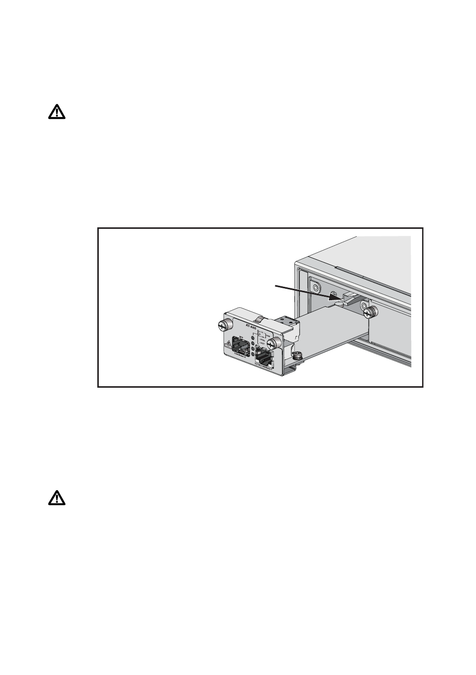
5. Slide the expansion module into place.
Make sure the module is aligned with the card guides on each side of the bay.
Slide the expansion module into the slot until the module face-plate makes
contact with the switch.
6. Secure the expansion module to the switch.
Firmly press the expansion module until its connectors engage the expansion
bay connectors inside the switch. Use a screwdriver to tighten the expansion
module’s screws. Do not over-tighten the screws.
7. Install the SFP if desired
Warning Do not look into the optical ports of SFP cables or transceivers.
Invisible laser radiation may be emitted from disconnected fibres or connectors.
You must insert the SFP transceiver with the release lever hinge at the bottom.
See the following figure as a guide.
To insert an SFP transceiver, slide the transceiver into the SFP socket, and firmly
press it until it engages. To remove an SFP transceiver, first release it by gently
pulling the release lever, then pull it out of the socket. Never force a transceiver
into or out of a socket.
switch_module.eps
card guide