Stack topology, Figure 2: duplex-chain topology – Allied Telesis AT-S63 User Manual
Page 70
Chapter 2: AT-9400Ts Stacks
70
Section I: Basic Operations
Stack Topology
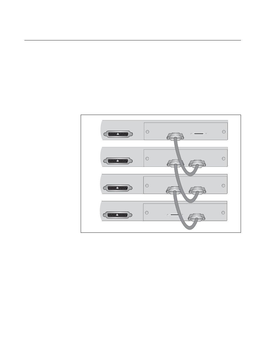
The switches of an AT-9400Ts Stack are cabled with the AT-StackXG
Stacking Module and its two full-duplex, 12-Gbps stacking ports. There
are two supported topologies. The first topology is the duplex-chain
topology, where a port on one stacking module is connected to a port on
the stacking module in the next switch, which is connected to the next
switch, and so on. The connections must crossover to different numbered
ports on the modules. Port 1 on the stacking module in one switch must be
connected to Port 2 on the stacking module in the next switch. An example
of this topology of a stack of four switches is illustrated in Figure 2.
Figure 2. Duplex-chain Topology
The second topology, the duplex-ring topology, is identical to the daisy-
chain, except that the stacking module in the switch at the top of the stack
is connected to the stacking module in the switch at the bottom of the
stack to form a physical loop. An example of this topology is shown in
Figure 3.
RPS INPUT
AT-StackXG
STACK PORT 1
STACK PORT 2
RPS INPUT
AT-StackXG
STACK PORT 1
STACK PORT 2
RPS INPUT
AT-StackXG
STACK PORT 1
STACK PORT 2
RPS INPUT
AT-StackXG
STACK PORT 1
STACK PORT 2
1246