Important, Back-to-back installation – Acorn SV16 VALVE User Manual
Page 5
Page 5 of 8
1. For 2” x 6” wall construction position shower
valve so that center of inlet ports are 2-1/8” ±
1/2” (50mm ± 13mm) from finished wall
ensuring the outlet port marked “T” is facing
down.
2. For 2” x 4” wall construction position shower
valve so that center of inlet ports are 1-3/8” ±
1/4” (50mm ± 6mm) from finished wall
ensuring the outlet port marked “T” is facing
down.
3. Make up connections to the appropriate inlet
ports, marked “H” and “C” on one valve and
reverse on the other, cold supply to “H” and hot
supply to “C”. Inlet connections are
combination 1/2” NPT and 1/2” sweat. Refer to
page 6 for cartridge removal and reversal.
4. To continue installations follow steps 4-9A on
page 4 or 9B on page 5.
To avoid confusion Hot and Cold inlets need to
be re-identified for future maintenance.
!
IMPORTANT
Excessive overheating of valve during soldering
may damage the cartridge and checkstops. Do
not heat valve any higher than needed to flow
solder. If a higher temperature method is being
used all internal components must be
removed. See figures 8 for cartridge removal
and 10 for temperature limit setting.
!
IMPORTANT
BACK-TO-BACK INSTALLATION:
Acorn Controls
Division of Acorn Engineering Company
®
, A member of Morris Group International
™
VALVE TRIM INSTALLATION CONTINUES:
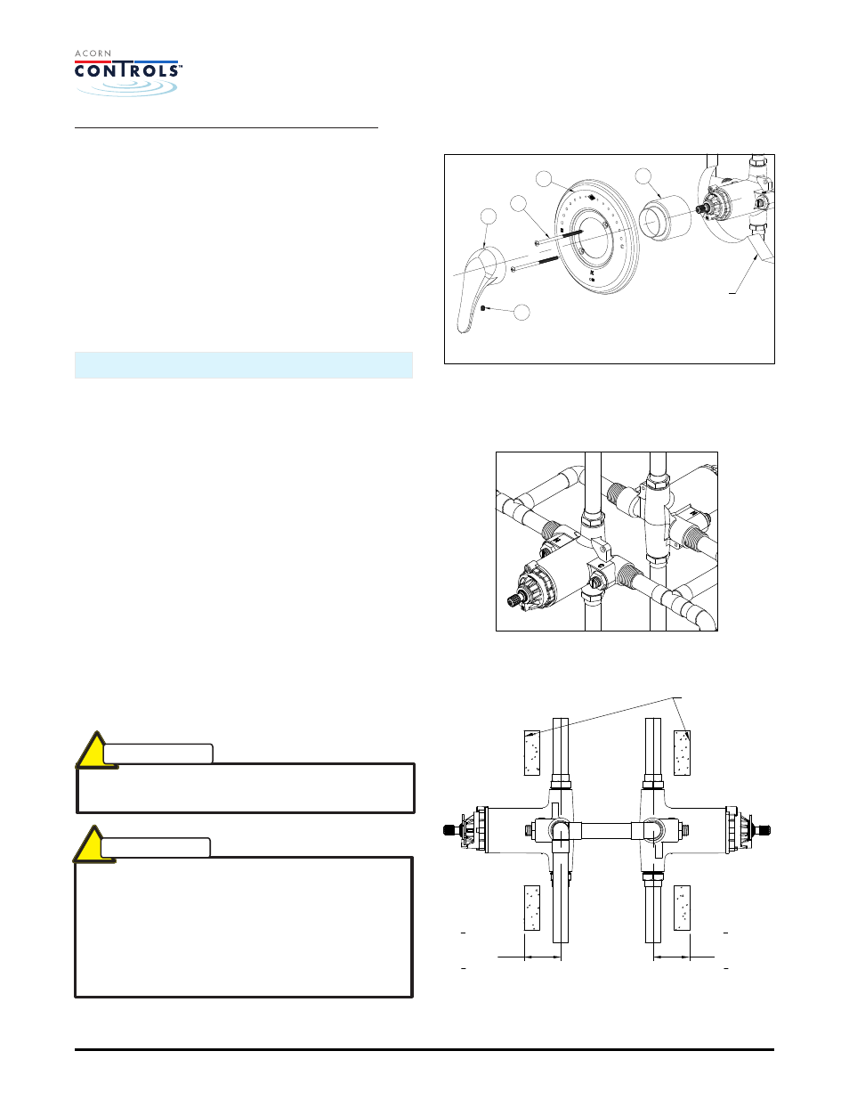
9B. SV16-LVR Valve Trim Installation:
Figure 7.
a. Slide valve sleeve 12 over valve body and
gasket 7.
b. Place escutcheon with gaskets 6 over
valve sleeve 12 and against finished wall
and secure with screws 8.
c. Push handle 13 onto valve stem and
secure with set screw 14.
BACK TO BACK DETAIL
HO
T
CO
LD
VIEW FROM REVERSED SIDE
2" X 6" BACK-TO-BACK
INSTALLATION
1
3
4
" (44)
MIN.
2
1
2
" (64)
MAX.
FINISHED
WALL
1
3
4
" (44)
MIN.
2
1
2
" (64)
MAX.
Manual #7802-116-000
Date: 07/10/14
FINISHED
WALL
13
8
6
12
14
FIGURE 7
SV16 Installation & Operation Manual