42 chapter 2: hardware information, Dsbv-d system panel auxiliary connector aux_panel1 – Asus Motherboard DSBV-D User Manual
Page 62
2-42
Chapter 2: Hardware information
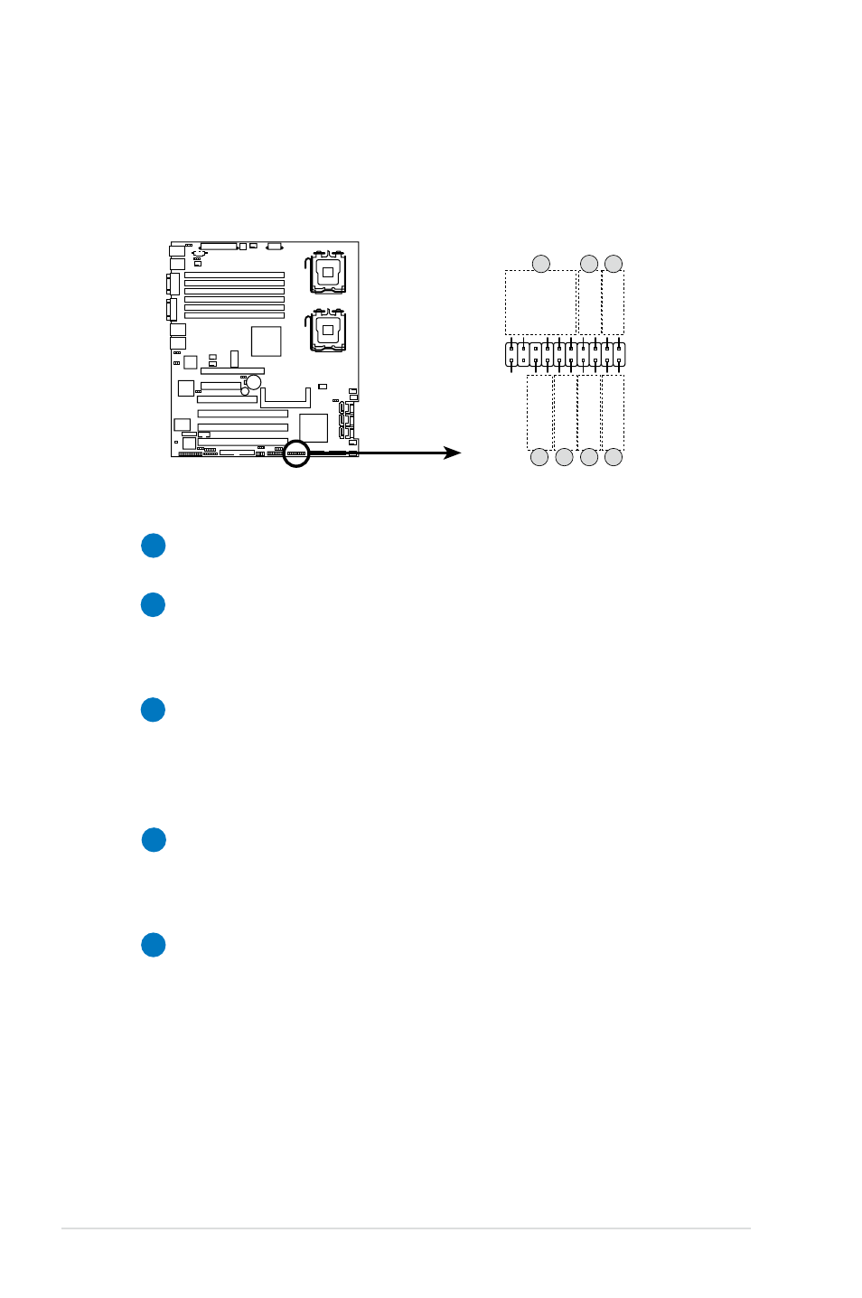
14. System panel auxiliary connector (20-2 pin AUX_PANEL1)
This connector is for additional front panel features including front panel SMB,
locator LED and switch, chassis intrusion, and LAN LEDs.
DSBV
-D
DSBV-D System panel auxiliary connector
AUX_PANEL1
I2C_4_D
AT
A#
LOCA
TORLED1+
+5VSB
LOCA
TORLED1-
LAN1_LINK
LOCA
TORBTN#
LAN1_ACT
GND
+5VSB
I2C_4_CLK#
GND
GND
LAN2_ACT
LOCA
TORLED2-
LAN2_LINK
LOCA
TORLED2+
CASEOPEN
PIN1
NC
1
2
2
5
4
3
4
1
Front panel SMB (6-1 pin FPSMB)
These leads connect the front panel SMBus cable.
2
LAN activity LED (2-pin LAN1_LINKACTLED, LAN2_LINKACTLED)
These leads are for Gigabit LAN activity LEDs on the front panel.
Connect the LAN Activity LED cables to these connectors. The LEDs
blink during a network activity and are always lit when linked.
3
Chassis intrusion (4-1 pin CHASSIS)
These leads are for the intrusion detection feature for chassis with
intrusion sensor or microswitch. When you remove any chassis
component, the sensor triggers and sends a high-level signal to these
leads to record a chassis intrusion event.
4
Locator LED (2-pin LOCATORLED1 and 2-pin LOCATORLED2)
These leads are for the locator LED1 and LED2 on the front panel.
Connect the Locator LED cables to these 2-pin connector. The LEDs
will light up when the Locator button is pressed.
5
Locator Button/Swich (2-pin LOCATORBTN)
These leads are for the locator button on the front panel. This button
queries the state of the system locator.