Asus Motherboard P5RD1-V User Manual
Page 51
A S U S P 5 R D 1 - V
A S U S P 5 R D 1 - V
A S U S P 5 R D 1 - V
A S U S P 5 R D 1 - V
A S U S P 5 R D 1 - V
2 - 3 1
2 - 3 1
2 - 3 1
2 - 3 1
2 - 3 1
1 0 .
1 0 .
1 0 .
1 0 .
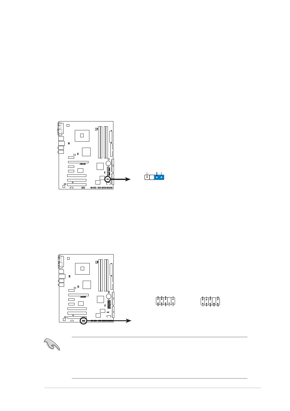
1 0 . Chassis intrusion connector (4-1 pin CHASSIS)
C h a s s i s i n t r u s i o n c o n n e c t o r ( 4 - 1 p i n C H A S S I S )
C h a s s i s i n t r u s i o n c o n n e c t o r ( 4 - 1 p i n C H A S S I S )
C h a s s i s i n t r u s i o n c o n n e c t o r ( 4 - 1 p i n C H A S S I S )
C h a s s i s i n t r u s i o n c o n n e c t o r ( 4 - 1 p i n C H A S S I S )
This connector is for a chassis-mounted intrusion detection sensor or
switch. Connect one end of the chassis intrusion sensor or switch
cable to this connector. The chassis intrusion sensor or switch sends a
high-level signal to this connector when a chassis component is
removed or replaced. The signal is then generated as a chassis
intrusion event.
By default, the pins labeled “Chassis Signal” and “Ground” are shorted
with a jumper cap. Remove the jumper caps only when you intend to
use the chassis intrusion detection feature.
1 1 .
1 1 .
1 1 .
1 1 .
1 1 . Front panel audio connector (10-1 pin AAFP)
F r o n t p a n e l a u d i o c o n n e c t o r ( 1 0 - 1 p i n A A F P )
F r o n t p a n e l a u d i o c o n n e c t o r ( 1 0 - 1 p i n A A F P )
F r o n t p a n e l a u d i o c o n n e c t o r ( 1 0 - 1 p i n A A F P )
F r o n t p a n e l a u d i o c o n n e c t o r ( 1 0 - 1 p i n A A F P )
This connector is for a chassis-mounted front panel audio I/O module
that supports either HD Audio or legacy AC ‘97 audio standard.
Connect one end of the front panel audio I/O module cable to this
connector.
•
Use a chassis that provides a high-definition audio front panel audio
I/O to use the high-definition audio features.
•
The default setting of this connector is legacy AC’97 audio, if you
want to use the High-Definition (Azalia) audio features, set the
A C 9 7 & A z a l i a L I N K A
A C 9 7 & A z a l i a L I N K A
A C 9 7 & A z a l i a L I N K A
A C 9 7 & A z a l i a L I N K A
A C 9 7 & A z a l i a L I N K A in the BIOS to Azalia. See page 4-26.
P5RD1-V
®
P5RD1-V Chassis intrusion connector
CHASSIS
+5VSB_MB
Chassis Signal
GND
(Default)
P5RD1-V
®
P5RD1-V Analog front panel connector
AAFP
Legacy AC’97-compliant
pin definition
Azalia-compliant
pin definition
SENSE2_RETUR
POR
T1 L
POR
T2 R
POR
T2 L
SENSE1_RETUR
SENSE_SEND
POR
T1 R
PRESENCE#
GND
NC
MIC2
Line out_R
Line out_L
NC
NC
MICPWR
NC
AGND