Allied Air Enterprises WARM AIR GAS FURNACE 92G1UH User Manual
Page 26
506724-01
Page 26 of 57
Issue 1108
Details of Intake and Exhaust Piping Terminations for
Direct Vent Installations
NOTE: In Direct Vent installations, combustion air is taken
from outdoors and flue gases are discharged to outdoors.
NOTE: Flue gas may be slightly acidic and may adversely
affect some building materials. If any vent termination is
used and the flue gases may impinge on the building
material, a corrosion-resistant shield (minimum 24 inches
square) must be used to protect the wall surface. If the
optional tee is used, the protective shield is required. The
shield should be constructed using wood, plastic, sheet metal
or other suitable material. All sems, joints, cracks, etc. in
the affected area should be sealed using an appropriate
sealant. See Figure 32.
Intake and exhaust pipes may be routed either horizontally
through and outside wall or vertically through the roof. In
attic or closet installations, vertical termination through the
roof is preferred. Figures 30 through 38 show typical
terminations.
1. Exhaust and intake exits must be in same pressure zone.
Do not exit one through the roof and one on the side.
Also, do not exit the intake on one side and the exhaust
on another side of the house or structure.
2. Intake and exhaust pipes should be placed as close
together as possible at termination end (refer to
illustrations). Maximum separation is 3” (76 mm) on
roof terminations and 6” (152 mm) on sidewall
terminations.
3. On roof terminations, the intake piping should terminate
straight down using two 90° elbows (See Figure 30).
4. Exhaust piping must terminate straight out or up as
shown. A reducer may be required on the exhaust piping
at the point where it exits the structure to improve the
velocity of exhaust away from the intake piping. See
Table 6.
NOTE: Care must be taken to avoid recirculation of exhaust
back into intake pipe.
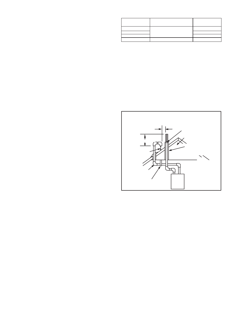
FIGURE 30
UNCONDITIONED
ATTIC SPACE
1/2" (13mm) FOAM
INSULATION IN
UNCONDITIONED
SPACE
SIZE TERMINATION
PIPE PER TABLE 6.
3"(76mm) MAX.
12" (305mm) ABOVE
AVERAGE SNOW
ACCUMULATION
3" (76mm) OR
2" (51mm) PVC
PROVIDE SUPPORT
FOR INTAKE AND
EXHAUST LINES
8" (203mm) MIN
Inches(mm)
DIRECT VENT ROOF TERMINATION KIT
(15F75 or 44J41)
(IF REQUIRED)
TABLE 6
EXHAUST PIPE TERMINATION SIZE REDUCTION
MODEL
Exhaust Pipe Size
Termination
Pipe Size
*045 and 070
2" (51mm), 2−1/2" (64mm),
3" (76mm)
1−1/2" (38mm)
*090
2" (51mm)
110
2" (51mm)
135
3" (76mm)
2" (51mm)
*−045, −070 and −090 units with the flush mount
termination must use the 1 1/2"accelerator supplied with the
kit.