Allied Air Enterprises WARM AIR GAS FURNACE 92G1UH User Manual
Page 21
506724-01
Page 21 of 57
Issue 1108
Intake Piping (Figures 24 through 27)
This gas furnace may be installed in either direct vent or
non-direct vent applications. In non-direct vent
applications, when intake air will be drawn into the furnace
from the surrounding space, the indoor air quality must be
considered and guidelines listed in Combustion, Dilution
and Ventilation Air section must be followed.
Follow the next two steps when installing the unit in Direct
Vent applications, where combustion air is taken from
outdoors and flue gases are discharged outdoors. The
provided air intake screen must not be used in direct
vent applications (outdoors).
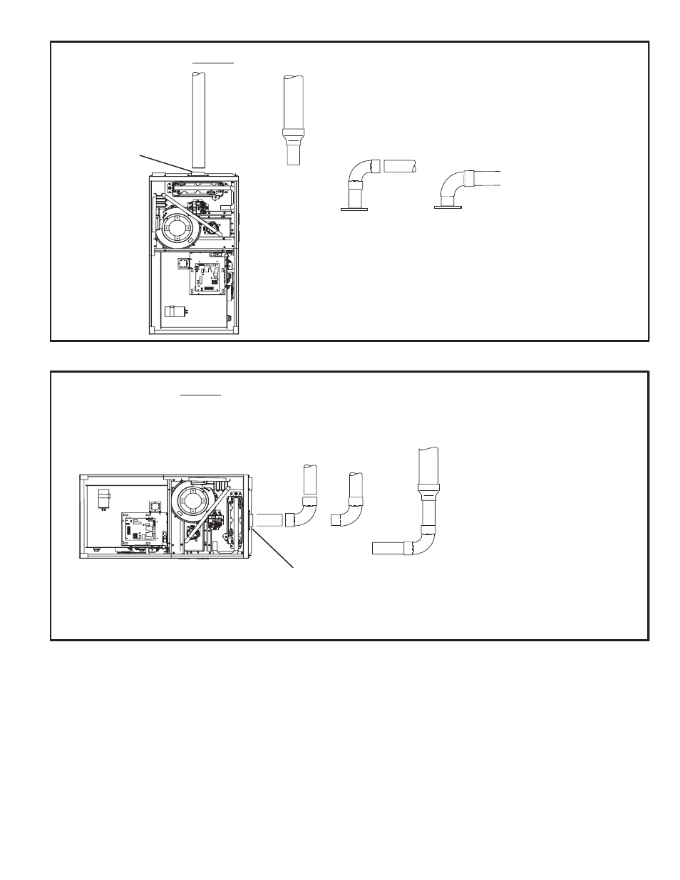
FIGURE 24
TYPICAL AIR INTAKE PIPE CONNECTIONS IN UPFLOW DIRECT VENT APPLICATIONS
*2”
TRANSITION
2”
3”
Pipe size determined in table 5
2”
2”
2”
2”
or
AIR INTAKE
* When transitioning up in pipe size, use the shortest length of 2” PVC pipe possible.
NOTE − Intake and exhaust pipe must be the same diameter.
or
FIGURE 25
TYPICAL AIR INTAKE PIPE CONNECTIONS IN HORIZONTAL DIRECT VENT APPLICATIONS
(RIGHT HAND DISCHARGE SHOWN)
2”
2”
2”
2”
or
TRANSITION
3”
2”
AIR INTAKE
* When transitioning up in pipe size, use the shortest length of 2” PVC pipe possible.
NOTE − Intake and exhaust pipe must be the same diameter.
*2"
*2"