Worlddsl, Hdsl, Features – ADC Double Pair/Line Power HDSL User Manual
Page 2
11/08
•
106805AE
W
orldDSL
™
HDSL
WorldDSL
™
HDSL
Economical, Reliable, and Manageable E1 and Serial Data Deployment
2
w w w . a d c . c o m
•
+ 1 - 9 5 2 - 9 3 8 - 8 0 8 0
•
1 - 8 0 0 - 3 6 6 - 3 8 9 1
Features
Fiber optic quality (BER 10
•
-10
)
LTUs can provide line powering for up to two
•
doublers for very long reach loops
LTUs can provide wetting current to reduce
•
corrosion of connections
Point-to-multipoint configurations where a single
•
central office card can operate two 1 Mbps
remote NTUs each via a single twisted pair to
reduce system costs
User software selectable dataport interface
•
Single pair mode where the unit uses only one pair
•
at a maximum rate of 1Mbps
Timeslot priority mode where, if one of the two
•
HDSL pairs fails, the FAS, signaling and first 15 voice
channels are switched to the operating pair
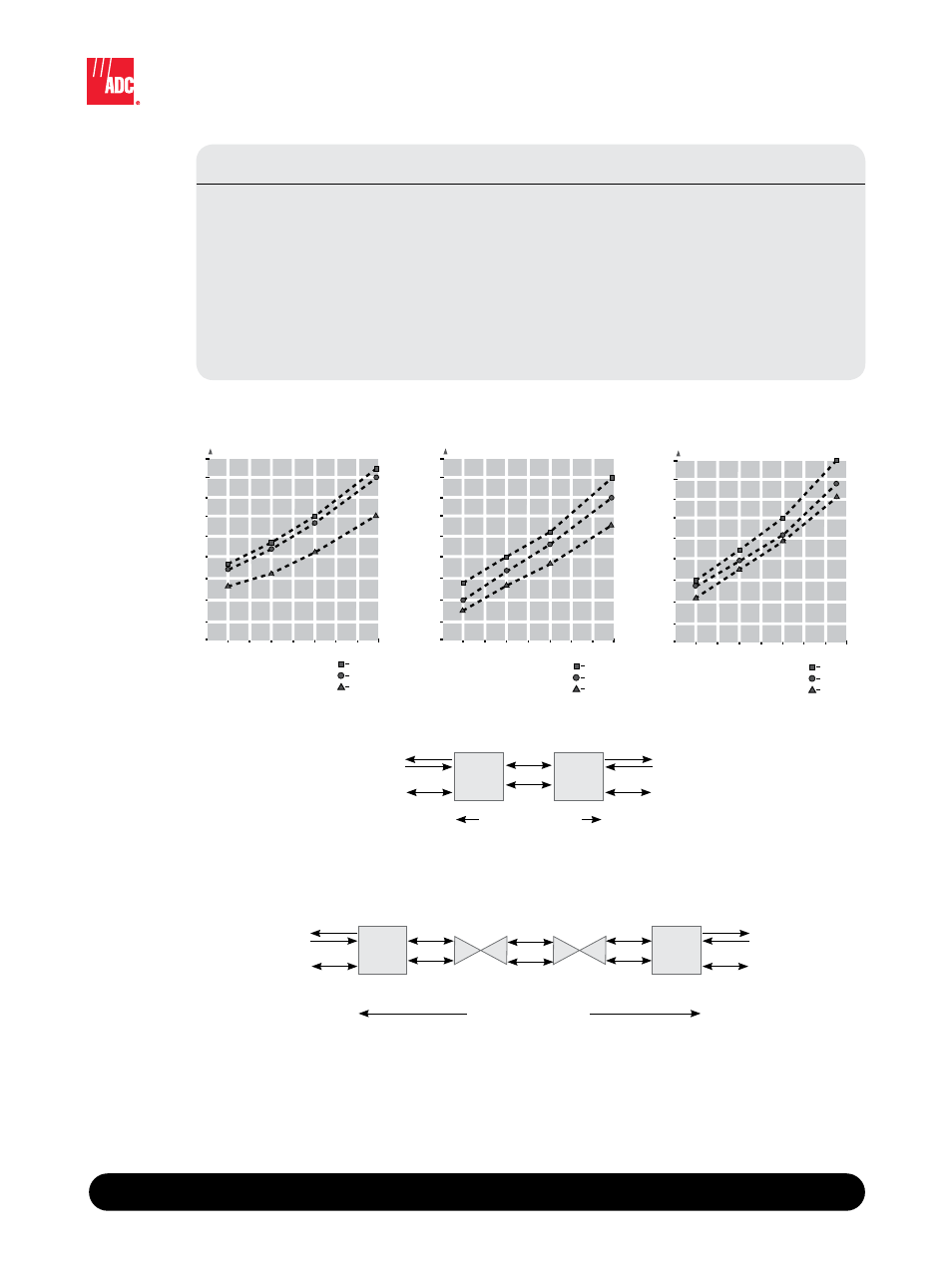
0.91 mm
0.40 mm 0.51 mm 0.64 mm
1
0
2
3
4
5
6
7
RANGE (KILOMETERS)
MAXIMUM
TYPICAL
MINIMUM
9
8
Wire Gauge (mm)
Figure 1
Single Span Reach
0.91 mm
0.40 mm 0.51 mm 0.64 mm
4
2
6
8
10
12
14
16
RANGE (KILOMETERS)
MAXIMUM
TYPICAL
MINIMUM
20
18
Wire Gauge (mm)
Figure 3
3 Span Two Doublers Reach
0.91 mm
0.40 mm 0.51 mm 0.64 mm
RANGE (KILOMETERS)
MAXIMUM
TYPICAL
MINIMUM
4
2
6
8
10
12
14
16
20
18
Wire Gauge (mm)
Figure 2
2 Span Single Doubler Reach
0.91 mm
0.40 mm 0.51 mm 0.64 mm
1
0
2
3
4
5
6
7
RANGE (KILOMETERS)
MAXIMUM
TYPICAL
MINIMUM
9
8
Wire Gauge (mm)
Figure 1
Single Span Reach
0.91 mm
0.40 mm 0.51 mm 0.64 mm
4
2
6
8
10
12
14
16
RANGE (KILOMETERS)
MAXIMUM
TYPICAL
MINIMUM
20
18
Wire Gauge (mm)
Figure 3
3 Span Two Doublers Reach
0.91 mm
0.40 mm 0.51 mm 0.64 mm
RANGE (KILOMETERS)
MAXIMUM
TYPICAL
MINIMUM
4
2
6
8
10
12
14
16
20
18
Wire Gauge (mm)
Figure 2
2 Span Single Doubler Reach
G.703
120/75Ω
Serial
V.35/V.36/RS-530/X.21
G.703
120/75Ω
Serial
V.35/V.36/RS-530/X.21
LTU or
UTU
UTU*
UTU**
LTU
7.5 Km on 0.4 mm
12.5 Km on 0.64 mm
3.2 Km on 0.4 mm
5.3 Km on 0.64 mm
E1 (G.703)
120/75Ω
Serial
V.35/V.36/RS-530/X.21
E1 (G.703)
120/75Ω
Serial
V.35/V.36/RS-530/X.21
Typical Single Span Applications
Typical 3-Span Extended Reach with doublers line powered and remote UTU locally powered
EDU
EDU
* Can be line powered from LTU or AC or DC local powered
** AC or DC local power required