Addressing, Operational modes – Campbell Scientific SDM-AO4A Four Channel Analog Output Module User Manual
Page 8
SDM-AO4A Four Channel Analog Output
5. Addressing
The SDM-AO4A is a synchronously addressed datalogger peripheral. Control
Ports 1, 2, and 3, are used to address an SDM-AO4A and send out the digital
millivolt settings for subsequent analog output. Addressing allows multiple
SDM peripherals to be connected to one datalogger.
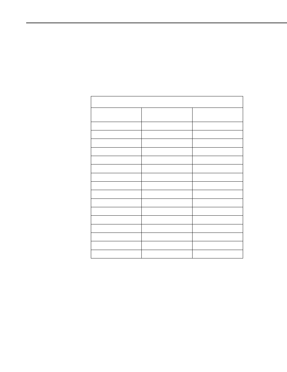
The SDM-AO4A has sixteen possible addresses, as shown in Table 2. The
address is hardware selectable using the rotary switch on the SDM-AO4A. All
SDM-AO4As are shipped with the address set at zero.
TABLE 2. SDM-AO4A Addressing
Base 10
[CRBasic Loggers]
Base 4 [CR10(X), 21X,
CR23X]
Rotary
Switch
0 0 0
1 1 1
2 2 2
3 3 3
4 10 4
5 11 5
6 12 6
7 13 7
8 20 8
9 21 9
10 22 A
11 23 B
12 30 C
13 31 D
14 32 E
15 33 F
6. Operational Modes
The SDM-AO4A can be operated in ±5 V mode or 10 V mode. In each of
these modes, the SDM-AO4A can operate synchronously or sequentially.
In synchronous mode, all channels are set at the same time. This mode is
slower since for large changes in voltage it may take multiple charging cycles
to arrive at the final voltage. The steps occur at 5 ms intervals, thus, for a 10V
step in output voltage it may take up to three charge cycles (or 15 ms) to settle
to the 16-bit level. For most slowly changing signals, it will settle in a single
charge cycle.
4