2 sdmspeed instruction – Campbell Scientific SDM-AO4 4-Channel Continuous Analog Output Module User Manual
Page 11
SDM-AO4 Four Channel Analog Output
SDMAddress: The SDMAddress parameter defines the address of the SDM-
AO4 to which a voltage should be applied. Valid SDM addresses are 0 through
14. Address 15 is reserved for the SDMTrigger instruction. CRBasic
dataloggers use base 10 when addressing SDM devices (see Table 2).
6.1.2 SDMSpeed Instruction
The SDMSpeed instruction is used to change the bit period that the datalogger
uses to clock the SDM data. Slowing down the clock rate may be necessary
when long cable lengths are used to connect the datalogger and SDM devices.
The syntax of this instruction is as follows:
SDMSpeed (
BitPeriod
)
The BitPeriod argument can be an integer or a variable. If the SDMSpeed
instruction is not in the program, a default bit period is used. If 0 is used for
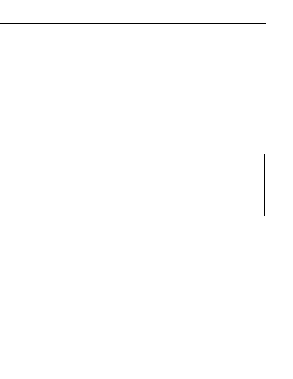
the argument, the minimum allowable bit period is used. Table 3 shows the
default, minimum allowable, and maximum bit period for each of our CRBasic
dataloggers.
TABLE 3. Bit Period Values
Datalogger
Default
Bit Period
Minimum Allowable
Bit Period
Maximum
Bit Period
CR800, CR850 26.04
μsec 8.68
μsec
2.2 msec
CR1000
26.04
μsec 8.68
μsec
2.2 msec
CR3000
26.04
μsec 8.68
μsec
2.2 msec
CR5000
30
μsec 8
μsec
3 msec
The equation used to calculate the bit rate depends on the datalogger used.
The datalogger will round down to the next faster bit rate.
Equation for CR800, CR850, and CR1000:
bit_rate=INT((k*72)/625)*Resolution
Where:
k= the value entered in BitPeriod
Resolution=8.68 microseconds
Equation for CR3000:
bit_rate=INT((k*144)/625)*Resolution
Where:
k= the value entered in BitPeriod
Resolution= 4.34
μsec.
7