Campbell Scientific SC100 1-Channel Serial Data Interface User Manual
Page 5
SC100 ISOLATED RS-232 BAUD RATE CONVERTER INTERFACE
3
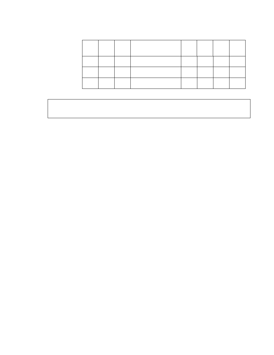
Parameters
Port Function
Configuration
number
3
6
8
DTR
CTS
TX
RX
1. DTR, RX
1
0
NZ
C
NC
NC
C+1
2. DTR,TX
1
NZ
0
C
NC
C+1
NC
4. DTR, TX, RX
1
NZ
NZ
C
NC
C+1
C+2
NOTE: Configuration numbers 2 & 4 have transmit (Tx) on the same control port (c+1). This is
useful if you plan to initialize the SC100 and receive data without having to change the control port
functions.
Choosing value for bit3 (half/full):
1) If the half duplex version and configuration
number 2 or/and 4 are used, then bit3 must
be 1.
2) If the full duplex version and configuration
number 2 or /and 4 are used, then bit3 must
be 0.
3) If configuration number 1 is used, then bit3
must be 0 for either half or full duplex.
Bit2 (parity/none) when this bit is set to one,
then either even or odd parity (depending on bit
4) will be enabled for the computer/sensor side.
Pig tail to DB 9 pin cable
Red
supply volts (jumper configurable to
either +12 V or +5 V)
Black
Gnd
Blue
DTR input
Orange
TXD input
Brown
RXD output
Green
FLAG output (SC100's output that
indicates buffered information ready)
Yellow
Power Down wire (+5 V will power
down the SC100 if internal jumper is
connected, connect to gnd if not
used). There are three different
power modes.
1) Yellow wire tied low (gnd) normal
operation mode ~55ma.
2) Yellow wire high (+5 V), Red wire
+12 V, power down mode ~ 2ma
3) Yellow wire high (+5 V), Red wire
+5 V power down mode >50
Micro Amps
Examples of connecting Pig tail cable to
datalogger
Instruction 15 input/output configurations
Number 4 (refer to "15 control port serial"
manual, table 1) DTR, TX, RX with first control
port parameter 4 = 1
Red
+12 V or +5 V (check jumpers in the
SC100)
Black
Gnd
Blue
C1
Orange
C2
Brown
C3
Green
C4
Yellow
GND
Instruction 15 input/output configurations
Number 1 DTR, RX with first control port
parameter 4 = 1
Red
+12 V or +5 V
Black
Gnd
Blue
C1
Orange
no connect
Brown
C2
Green
C3
Yellow
GND