A.1.1.2 wiring, A.1.1.2, A.1.1.3 – Campbell Scientific GPS16X-HVS GPS Receiver User Manual
Page 22
Appendix A. Changing GPS16X-HVS Settings
Drivers should be loaded before plugging the A200 into the PC.
The A200 drivers can be downloaded, at no charge, from:
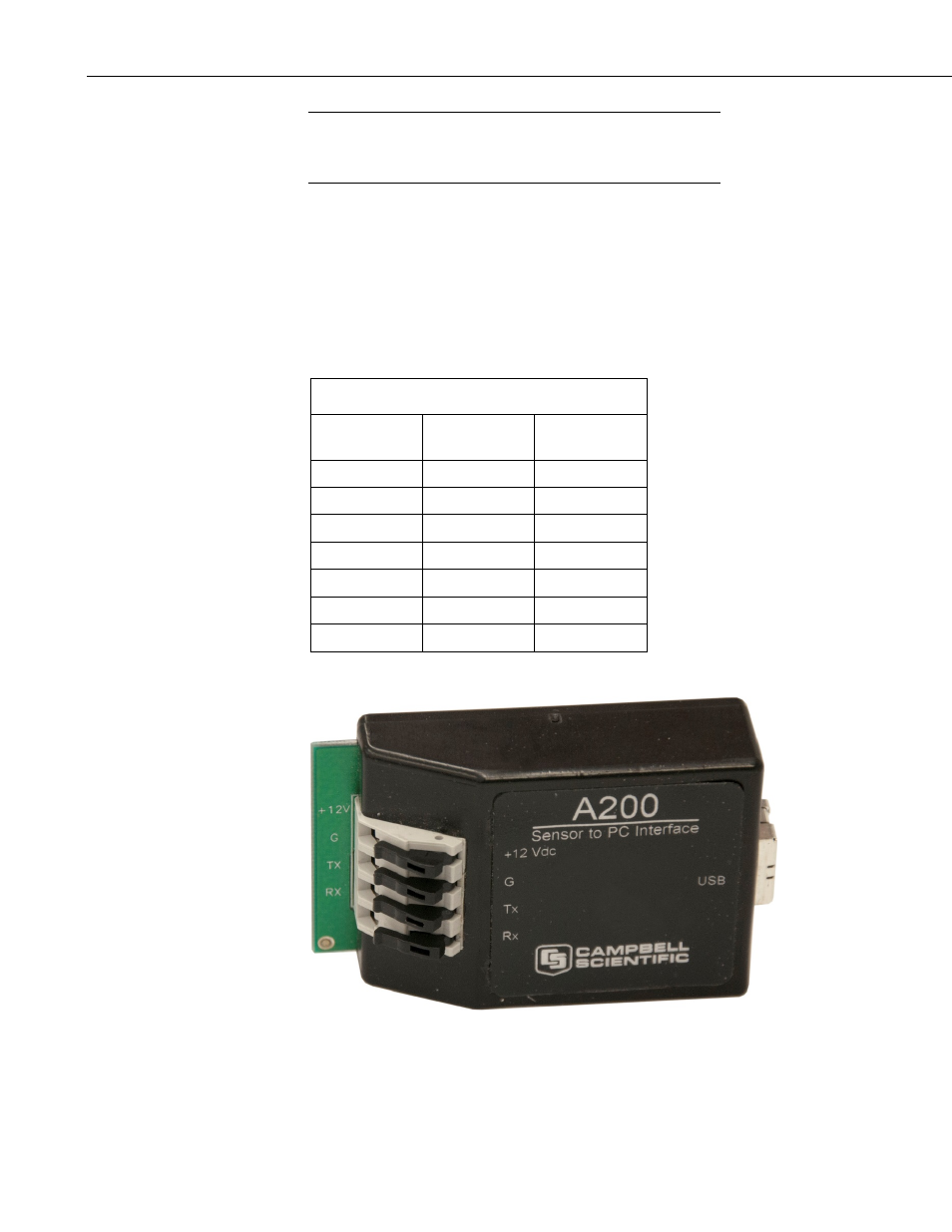
A.1.1.2 Wiring
One end of the A200 has a terminal block while the other end has a type B
female USB port. The terminal block provides 12V, G, TX, and RX terminals
for connecting the GPS16X-HVS (see FIGURE A-1 and TABLE A-1).
A data cable, CSI part number 17648, ships with the A200. This cable has a
USB type-A male connector that attaches to a PC’s USB port, and a type B
male connector that attaches to the A200’s USB port.
TABLE A-1. A200 Wiring
Color
Sensor
Cable Label
A200
Terminal
Red
12V
+12Vdc
Black
G
G
Yellow
G
G
White
Rx
Rx
Gray
Tx
Tx
Blue
sig ground
G
Shield
sig ground
G
FIGURE A-1. A200 Sensor-to-PC Interface
NOTE
A-2