2 powering the com320 modem, 3 grounding the com320 system, Com320 voice communications modem – Campbell Scientific COM320 Voice Communications Modem User Manual
Page 27: Cr1000
COM320 Voice Communications Modem
SE
1
2
3
4
5
6
7
8
H
1
2
3
4
L
DIFF
H
EX1
H
L
H
L
L
P2
P1
12V
G
DC ONLY
CAUTION
LUG
GROUND
POWER IN
WIRING PANEL
CR1000
PERIPHERAL PORT
RS-232 (Not Isolated)
SN:
CS I/O
MADE IN USA
11
10
9
SE
15 16
13 14
12
H
L
DIFF
H
EX2
H
L
H
L
L
EX3
5
6
7
8
SW
-12
5V
12V
12V
C5
C4
G
G
G
G
C1
C2
C3
G
G
C6
C7
C8
Tx
COM1
Rx Tx Rx
Tx Rx Tx Rx
COM2
COM3
COM4
POWER OUT
SDM
G 12V
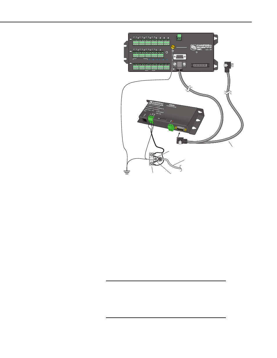
Burial Phone Cable
Blue = Ring
Blue/White = Tip
Phone Line
Transient Protector
(Model 6362 or 2372-01)
SC12 Cable
Earth
Ground
FIGURE 3. COM320 / CR1000 Using Surge Protection Device
(where there’s no available Standard RJ11 Connection)
6.2 Powering the COM320 Modem
The datalogger provides 12 VDC on the CS I/O connector’s pin 8 for powering
peripherals such as the COM320.
6.3 Grounding the COM320 System
Connect the green 14 AWG grounding wire (provided with the COM320) to
the GND terminal on the COM320 and to the station enclosure’s earth ground
connection. It is important that you connect the COM320 and datalogger
directly to a high quality earth ground. Read the datalogger manual section on
GROUNDING for details on creating such an earth ground.
A quality EARTH GROUND connection to the COM320
and datalogger maximizes protection against electro-
static discharge! Follow carefully the EARTH
GROUND scheme in Figure 4. The COM320 employs
spark gaps on the phone lines; however, they will be
ineffective without quality earth grounding.
WARNING
21