Wiring – Campbell Scientific CMP3 Pyranometer User Manual
Page 8
CMP3-L Pyranometer
4. Wiring
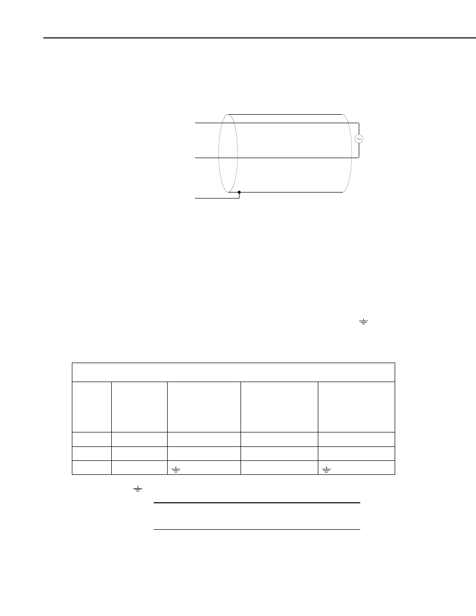
A schematic diagram of the CMP3-L is shown in Figure 4-1.
Red
Blue
Black
White
Black
Shield
FIGURE 4-1. CMP3-L Schematic
When Short Cut for Windows software is used to create the datalogger
program, the sensor should be wired to the channels shown in the wiring
diagram created by Short Cut.
A differential voltage measurement is recommended because it has better noise
rejection than a single-ended measurement. If a differential channel is not
available, a single-ended measurement can be used.
Connections to Campbell Scientific dataloggers for a Differential measurement
are given in Table 4-1. A user supplied jumper wire should be connected
between the low side of the differential input and ground (AG or
) to keep
the signal in common mode range.
Connections to Campbell Scientific dataloggers for a Single-Ended
measurement are given in Table 4-2.
TABLE 4-1. Differential Connections to Campbell Scientific Dataloggers
Color
Description
CR9000(X)
CR5000
CR3000
CR1000
CR800
CR510
CR500
CR10(X)
21X
CR7
CR23X
White
Signal (+)
DIFF Analog High
DIFF Analog High
DIFF Analog High
Black
Signal (-)
*DIFF Analog Low
*DIFF Analog Low
*DIFF Analog Low
Shield Shield
G
* Jumper to AG or
with user supplied wire.
A CMP3-L purchased from Campbell Scientific has different
wiring than a CMP3 purchased directly from Kipp & Zonen.
NOTE
4