Datalogger programming – Campbell Scientific 034A-L WindSet User Manual
Page 7
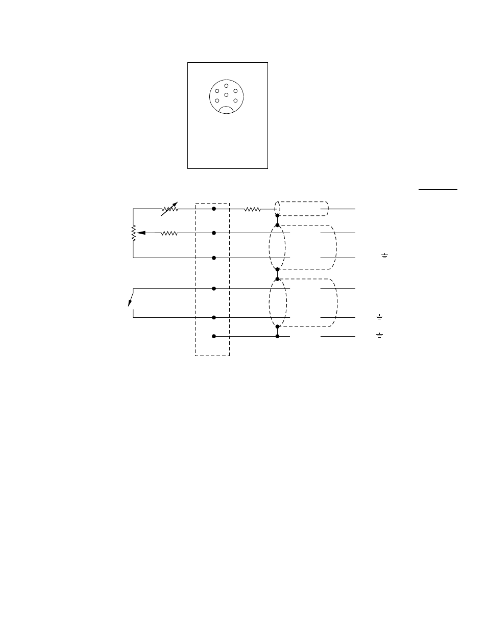
MET ONE 034A-L WINDSET
3
ADJUSTABLE
RESISTANCE
1
2
6
3
4
5
CONNECTOR PIN-OUT
PIN 1 - AZIMUTH SIGNAL
PIN 2 - AZIMUTH REFERENCE
PIN 3 - AZIMUTH EXCITATION
PIN 4 - PULSE OUT
PIN 5 - PULSE REFERENCE
PIN 6 - SHIELD
CONNECTOR
(PIN)
10K OHM AZIMUTH
POTENTIOMETER
MAGNETICALLY
ACTIVATED
REED SWITCH
1K OHM
9.53K OHM
3
1
2
4
5
6
BLUE
WHITE
GREEN
RED
BLACK
CLEAR
FIGURE 4-1. 034A-L Windset Wiring Diagram
5. DATALOGGER PROGRAMMING
The Pulse instruction, Instruction 3, with an
option code of 22, is used to measure the wind
speed. Instruction 3 counts the number of
switch closures that have occurred during the
datalogger’s execution interval. When option
code 22 is selected, the datalogger reports the
counts as a frequency. In addition, counts
beyond the execution interval, caused by table
overruns, are discarded, see Section 9 of the
Datalogger manual for details. The frequency is
converted into wind speed using the multiplier
and offset listed in Table 5-1.
The AC Half Bridge instruction, Instruction 5, is
used to measure wind direction. The AC Half
Bridge (P5) instruction provides a precision
voltage to the potentiometer and measures the
voltage between the wiper and ground. The
voltage is linearly proportional to the azimuth
and is converted to degrees by the multiplier
and offset listed in Table 5-1.
E3
SE5 or 3H
AG or
P2
G or
G or
(Switch
Excitation)
(Single-Ended
Analog Input)
(Pulse Input
Datalogger