2 connection, Connection sequence – Samlex America Solarix-PRS User Manual
Page 5
4.2.2 Connection
WARNING
Danger of explosion from sparking! Danger of electric shock!
Solar modules generate electricity under incident light. The full voltage is present, even
when the incident light levels are low.
Protect the solar modules from incident light during installation, e.g. cover them.
Never touch uninsulated cable ends.
Use only insulated tools.
Ensure that all loads to be connected are switched off. If necessary, remove the
fuse.
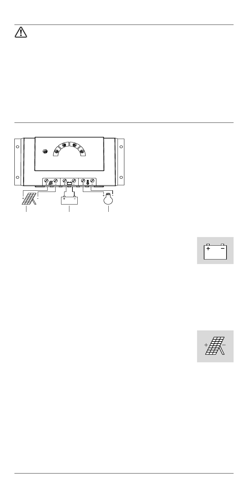
Connections must always be made in the sequence described below.
2
1
3
1st step: Connect the battery
Label the battery connection cables as a plus cable (A+) and a
minus cable (A–).
Lay the battery cables in parallel between the solar charge control-
ler and the battery.
Connect the battery connection cable with the correct polarity to the middle pair of
terminals on the solar charge controller (with the battery symbol).
If necessary, remove any external fuse.
Connect battery connection cable A+ to the positive pole of the battery.
Connect battery connection cable A– to the negative pole of the battery.
Replace the external fuse in the battery connection cable.
If the connection polarity is correct, the info LED illuminates green.
2nd step: Connect the solar module
Ensure that the solar module is protected from incident light.
Ensure that the solar module does not exceed the maximum per-
missible input current.
Label the solar module connection cables as a plus cable (M+) and
a minus cable (M–).
Lay both solar module connection cables in parallel between the solar module and
the solar charge controller.
First connect the M+ solar module connection cable to the correct pole of the left
pair of terminals on the solar charge controller (with the solar module symbol),
then connect the M– cable.
Remove the covering from the solar module.
Connection sequence
1. battery
. solar module
3. loads
5