Installation, 1 mounting the solar charge controller, 2 fastening the solar charge controller – Samlex America Solarix-PRS User Manual
Page 4: 2 connection 4.2.1 preparing the wiring
4. Installation
WARNING
Danger of explosion from sparking! Danger of electric shock!
The solar charge controller may only be connected to the local loads and the bat-
tery by trained personnel and in accordance with the applicable regulations.
Follow the installation and operating instructions for all components of the PV sys-
tem.
Ensure that no cables are damaged.
4.1 Mounting the solar charge controller
4.1.1
Mounting location requirements
Do not mount the solar charge controller outdoors or in wet rooms.
Do not subject the solar charge controller to direct sunshine or other sources of
heat.
Protect the solar charge controller from dirt and moisture.
Mount upright on the wall (concrete) on a non-flammable substrate.
Maintain a minimum clearance of 10 cm below and around the device to ensure
unhindered air circulation.
Mount the solar charge controller as close as possible to the batteries (with a safety
clearance of at least 30 cm).
4.1.2 Fastening the solar charge controller
Mark the position of the solar charge controller fastening holes on the wall.
Drill 4 Ø 6 mm holes and insert dowels.
Fasten the solar charge controller to the wall with the cable openings facing down-
wards, using 4 oval head screws M4x40 (DIN 7996).
4.2 Connection
4.2.1 Preparing the wiring
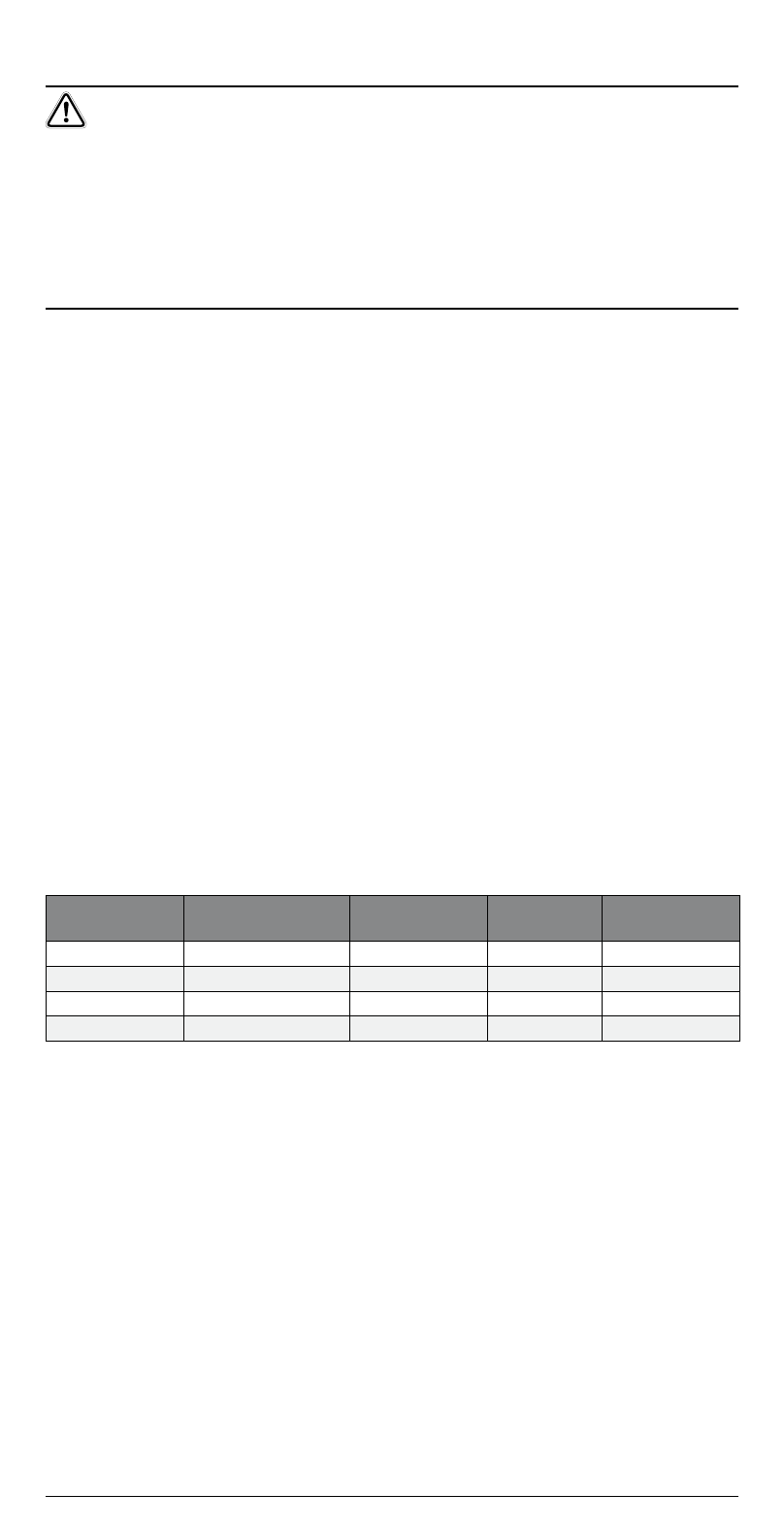
The cross section of the connection cable depends on the power output of the
solar charge controller.
Controller type
Load/module
current
Cross-section
AWG
Insulation
10 A
10 A
6 mm
10
85 °C
15 A
15 A
10 mm
8
85 °C
0 A
0 A
10 mm
8
85 °C
30 A
30 A
16 mm
6
85 °C
The table above applies to the following cable lengths:
10 m solar module connection cable
m battery connection cable
5 m load connection cable
Consult a dealer if the specified cable lengths are inadequate.
An additional external fuse (not provided) must be connected to the battery con-
nection cable, close to the battery pole.
The external fuse prevents cable short circuits. A 40 A fuse can be used for all controller
types.
•
•
•
•
•
•
•
•
•
4