Layout and input output connections – Samlex America Step 20 User Manual
Page 4
4 | SAMLEX AMERICA INC.
SeCtIOn 3 |
layout, Connections & Dimensions
Layout anD input output connectionS
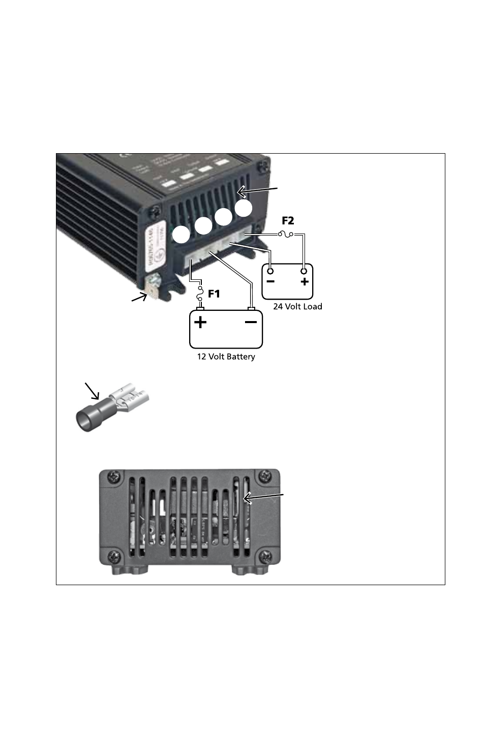
please refer to fig 1 for Step 7 and Step 10 and fig. 2 for Step 20
froNt VIeW
1
2
3
4
5
6
LeGeND:
*1. Input terminal: +12V
*2. Input terminal: -12V Common (-) Ground
*3. output terminal: -24V Common (-) Ground
*4. output terminal: +24V
5. System/earth Ground
6. Ventilation Slots
bACK VIeW
6
* Note:
a. terminals on the unit: Male, "Quick Connect"
Spade terminal - 6.3 mm / 0.25"
b. Use mating, female "Quick Connect" terminal shown
on the left for connecting wires (Not Supplied).
f1: input fuse
(not Supplied)
32V, fasting Acting
- Step 7: 25A
- Step 10: 35A
f2: output fuse
(not Supplied)
32V, fasting Acting
- Step 7: 7A
- Step 10: 10A
Fig. 1: Layout & Input / Output Connectins - STEP 7, STEP 10
Mating female
Quick Disconnect
for Wiring