ROHM Hydraulic collet chucks User Manual
Page 2
Dehnspannhlse
Spannen und Lösen des Werkzeuges!
Um eine fehlerhafte Funktion der Hydro-
Dehnspannfutter zu gewährleisten,
beachten Sie bitte folgende Anweisungen:
Verwendung von Zylinderschaftwerkzeuge
nach DIN 1835 und DIN 6535 Form (HA) und
B (HB) bis ¯ 20 Spannschaft mit Herstelltole-
ranz h6, feingeschliffen Ra
min
= 0,3. Schfte
nach DIN 6535 Form HE (Whistle Notch)
sind nur in Verbindung mit Reduzierstcken
einsetzbar. Alle Rotations-Dehnspannfutter
sind bis 15.000 min
Ð1
ab Werk Grundge-
wuchtet.
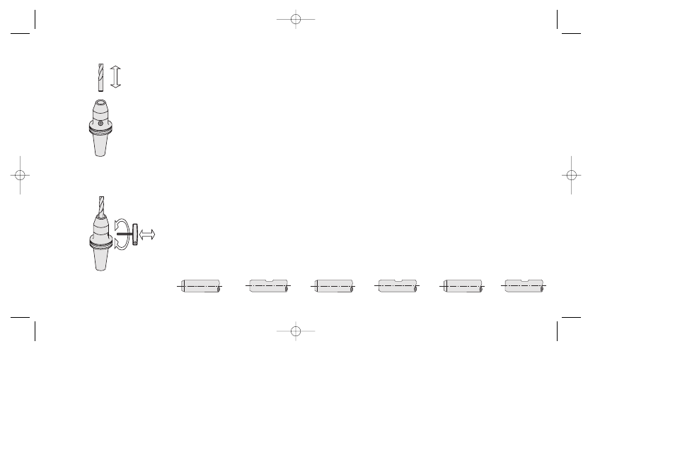
Spannen und lösen eines Werkzeuges
1.) Reinigen der Futteraufnahmebohrung und
Werkzeugschaft von Fett und Schmutz.
Werkzeugschaft bis zum Anschlag einfhren.
Mindesteinspannlnge und Verstellweg sind
unbedingt einzuhalten.
2.) Mit Sechskantschlssel im Uhrzeigersinn
die Spannschraube bis zum Anschlag
drehen. Das Werkzeug ist
Wegen
Bruchgefahr der
keine
Leerspannungen vornehmen.
3.) Zum Lsen des Werkzeuges Spann-
schraube ca. 5 bis 6 Umdrehungen zurck-
drehen und das Werkzeug entnehmen.
Diese Werte gelten fr Schfte nach DIN 1)
gespannt.
Clamping and releasing of the tool:
To ensure correct funcion of the hydraulic
expansion chuck. the following instructions
should be followed:
Use of cylinder shaft tools in accordance with
DIN 1835 and DIN 6535 shape (HA) and B
(HB), up to dia. 20 clamping shaft with manufac-
turing tolerance h6, finely-ground Ra
min.
= 0.3.
Shafts as per DIN 6535 shape HE (whistle
notch) can only be used in conjunction with re-
ducer elements. All rotation expansion chucks
are base-balanced up to 15,000 min
-1
at the
works.
Chucking and releasing a tool
1) Clean any grease and dirt off the chuck
mounting drillhole and the tool shaft. Guide the
tool shaft in as far as to the stop. It is essential
to respect the minimum chucking length and
adjustment path.
2) Using the hexagonal-headed key, rotate the
clamping screw in a clockwise direction as far
as to the stop. Do not attempt any empty clam-
ping movements due to the risk of breaking the
expansion clamping sleeve.
3) To release the tool, turn the clamping screw
back by about 5 or 6 revolutions and remove the
tool.
These values apply to shafts as per DIN 1)
Serrage et desserrage de l’outil:
pour assurer le bon fonctionnement du
mandrin à serrage hydraulique, veuillez
suivre les instructions suivantes:
Utilisation dÕoutils queue cylindrique suivant
DIN 1835 et DIN 6535, forme (HA) et B (HB),
avec queue jusquÕ ¯ 20, rectifie avec une
tolrance de fabrication h6, Ra
min
= 0,3. Les
queues suivant DIN 6535, forme HE (Whistle
Notch) ne peuvent tre utilises quÕavec des
douilles de rduction. Tous les mandrins sont
quilibrs juquÕ 15 000 tr/mn.
Serrage et desserrage d’un outil:
1.) Enlever la graisse et les impurets qui se
trouvent dans lÕalsage du mandrin et la queue
de lÕoutil. La longueur minimum de serrage et
la course de rglage doivent tre impratvment
respectes.
2.) Tourner la vis de serrage dans le sens des
aiguilles dÕune montre jusquÕen bute, lÕaide
de la cl fourche. LÕoutil est serr. Ne pas
faire dÕune cl 6 pans. LÕoutil est maintenant
serr. Ne pas serrer vide Ð risque de casse
de la membrane.
3.) Pour desserrer lÕoutil, dvisser la vis de ser-
rage dÕenvirons 5 6 tours et retirer de lÕoutil.
Ces valeurs sont valables pour les tiges
suivant DIN 1)
1
2
DIN 1835 A / DIN 6535 HA
DIN 1835 B / DIN 6535 HB
bis Ø 20 mm
1
2
DIN 1835 A / DIN 6535 HA
DIN 1835 B / DIN 6535 HB
to Ø 20 mm
1
2
DIN 1835 A / DIN 6535 HA DIN 1835 B / DIN 6535 HB
а Ш 20 mm
Abb. siehe Punkt 1 + 3
Abb. siehe Punkt 2
33377-k000-001 19.02.2002 13:02 Uhr Seite 1