Warning, Connections, 1 connector pinout – Matrix Orbital VK202-25 Legacy User Manual
Page 8: Do not apply any power with reversed polarization
VK202-25 rev. 05
8
2. Connections
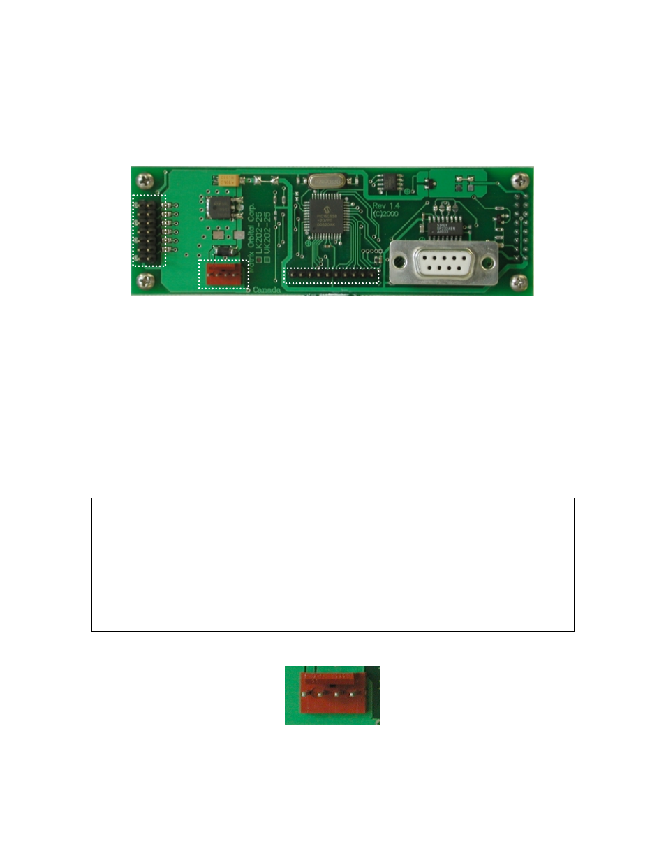
2.1 Connector Pinout
Refer to the diagram below for this chapter.
Keypad
Connector
Power
connector
General
Purpose
Outputs
RS-232
pin 1
+5
gnd
pin 1
pin 5
1
2
3
4
5
6
Figure 2-1 Electrical Connections
The VK202-25 has four connectors:
Connector Function
14 pin dual header
General purpose outputs (6) (see section 2.2)
4 pin
power (5.0 VDC) and I
2
C communications (see section 2.1.1)
10 pin header
Keypad (see section 3.4.12)
DB-9F
RS-232/power (see section 2.1.1.1)
2.1.1 Power and I
2
C Connections
Power is applied via pins 1 and 4 as shown in Figure 2-1. Power requirement is +5 VDC ±0.25V. Power
may also be supplied via the RS-232 connector as described in the next section.
Warning:
Do not apply any power with reversed polarization.
Do not apply any voltage other than the specified voltage.
Do not use any cables other than the cables supplied by Matrix Orbital,
unless you are aware of the modifications required.
Do not apply voltage to the DB-9 connector AND power connector
Do not apply more than +5Vdc to pin #9 on the DB-9 connector.
Connector pinout is as follows:
1 2 3 4
Figure 2-2 Power connector
Pin 1
+5.0 VDC (+7 to +15 VDC with wide voltage option)