Matrix Orbital LK202-25 Legacy User Manual
Page 3
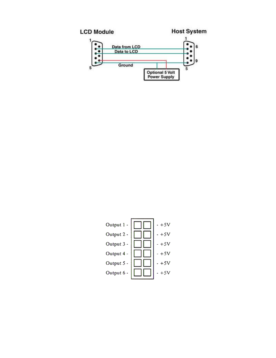
Power may be provided to the module by pin 9 of the DB9 connector instead of through the 4-pin SIP. If power is to be
applied using the DB9, it must be a regulated 5Vdc supply. If the user intends to use pin 9 as the power source, the user
must solder the 5 volt jumper point beside the DB9 connector. If you have any further questions or concerns don’t hesitate
to contact Matrix Orbital at [email protected].
Warning: Use this method of power up at your own risk. Application of a voltage to pin 9 greater than 5.5volts will cause
immediate destruction of unit and void the warranty.
Note: This applies to wide voltage units (V and VPT extensions) as well as to standard 5 volt units.
General Purpose Output (GPO)
Each of the GPO's are meant to be used as a pair. The positive side of the GPO's are connected to a power source of
+5Vdc supplied by the module at 20mA. The negative side of the GPO's are capable of finding a path to ground through a
240 ohm resistor. This resistor will limit the current flow through a GPO to approximately 20mA in the event of a short
circuit. If the device which is being driven by a GPO requires a relatively high current (such as a relay) and has an internal
resistance of it’s own greater than 250 ohms, then the 240 ohm resistor may be shorted. You will find this resistor directly
below the negative pin of the general purpose output.
Note: This operation requires soldering. The GPO's do not have any over current or over/under voltage protection so care
must be taken if the user decides to connect the negative side differently. For instance if the external device is a relay it must
be fully clamped to absorb any generated back electromotive force (EMF).
3