Matrix Orbital LK202-25 Legacy User Manual
Page 2
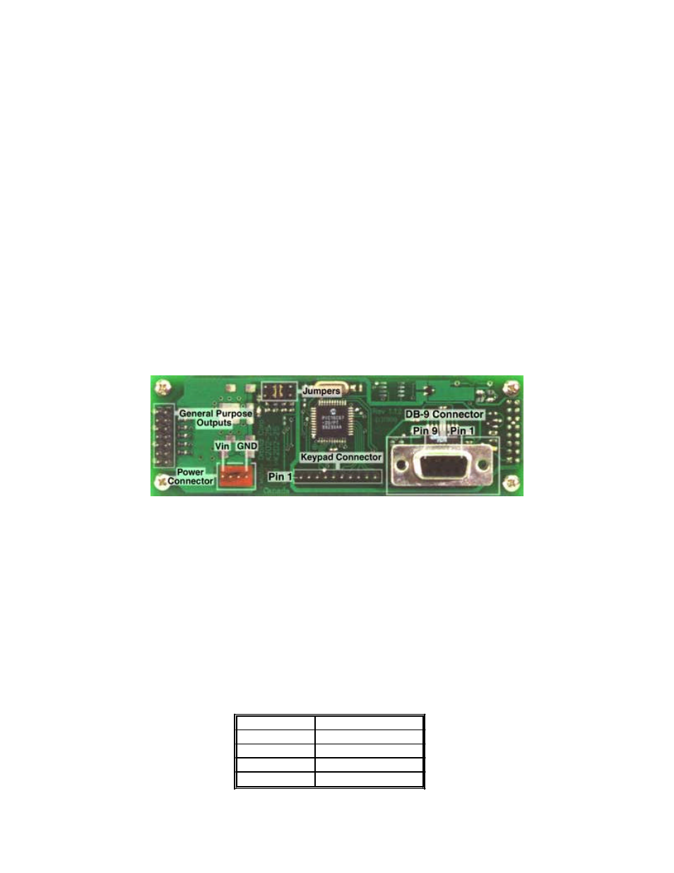
Connecting LK202-25
Regular Voltage
Power is applied to the white or brown four pin SIP connector as follows:
Pin 1: +5Vdc
Pin 2: = SCL (I²C clock)
Pin 3: = SDA (I²C data)
Pin 4: Gnd
If the sole data source is via the RS-232, the data input is via the DB9 connector. Pins 2 and 3 are not used.
Wide Voltage Option (V)
Power is applied to the white or brown four pin SIP connector as follows:
Pin 1: +7 - +15Vdc
Pin 2: = SCL (I²C clock)
Pin 3: = SDA (I²C data)
Pin 4: Gnd
If the sole data source is via the RS-232, the data input is via the DB9 connector. Pins 2 and 3 are not used
2
W
ARNING
:
D
O
NOT
APPLY
ANY
POWER
WITH
A
REVERSED
CABLE
.
D
O
NOT
APPLY
AN
VOLTAGE
OTHER
THAN
THE
SPECIFIED
VOLTAGE
.
D
O
NOT
USE
ANY
CABLES
OTHER
THAN
THE
CABLES
SUPPLIED
BY
M
ATRIX
O
RBITAL
,
UNLESS
YOU
ARE
AWARE
OF
THE
MODIFICATIONS
REQUIRED
.
D
O
NOT
UNDER
ANY
CIRCUMSTANCES
USE
AN
UNMODIFIED
FLOPPY
DRIVE
POWER
CABLE
.
DB9 Connector Pin Out
RS - 232 port: This connector is wired so that a standard “straight through” 9 pin D-sub cable may be used to connect the
modules on a standard serial port such as comm ports on PCs. Note that this device complies to the EIA232 standard in
that it uses signal levels from +/- 3V to +/- 12V. It will not operate correctly at TTL (0 to +5V) levels.
Note: Signals are shown as interpreted by the Liquid Crystal Display module.
Pin Number
Description
2
Data Out
3
Data In
5
Ground
9
+5Vdc