Aalborg AFC User Manual
Page 19
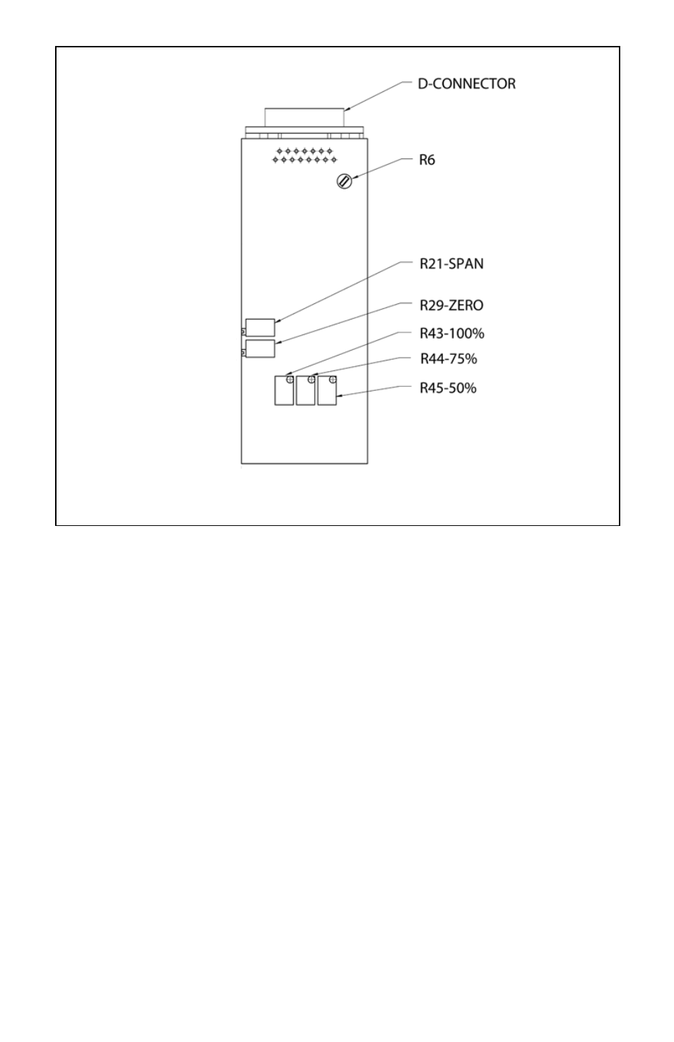
FIGURE 7-1, CALIBRATION POTENTIOMETER LOCATIONS
7.2
Calibration of AFM Mass Flow Meters
All adjustments in this section are made from the outside of the meter, there is no
need to disassemble any part of the instrument.
AFM Mass Flow Meters may be field recalibrated/checked for the same range
they were originally factory calibrated for. When linearity adjustment is needed, or
flow range changes are being made proceed to step 7.3. Flow range changes
may require a different Restrictor Flow Element (RFE). Additionally, a different
Solenoid Valve Orifice for the AFC Mass Flow Controller (see Table VI) may also
be required. Consult your distributor or Aalborg
7 for more information.
7.2.1
Connections and Initial Warm Up
Connect the multimeter to output pins* [2] and [3] of the 15-pin “D” connector for
0-5 VDC (or pins [5] and [15] for optional 4-20 mA) (see Figure 2-3).
* If you are calibrating a Mass Flow Meter System that incorporates a
DSPROC Command Module, the multimeter may be connected via the
DATA connector which is located at the back of the Command Module.
Power up the Mass Flow Meter for at least 30 minutes prior to commencing the
calibration procedure.
16