Part 1 installation, V piping – Midco J83-DS User Manual
Page 3
Part 1 Installation
Part 1
Installation
Continued
IV Chimney, Vent
Connector *
and Draft Control
*Formerly referred
to as Flue Pipe
3
To change the Mounting Flange to its alternate position, horizontal or 10° down firing, remove
the four (4) screws that attach it to the burner, rotate the flange 180° and reinstall the screws.
Before mounting the burner, check that the Blast Tube and Blower Housing are clear of foreign
material and that the Main Gas Port and Nozzle Support is clean and undamaged.
If the incinerator is located outdoors, the burner and all of its components, except the Main
Manual Shut-Off Valve, must be protected from weather. The Midco
®
Accessory Weatherhood will
provide such protection.
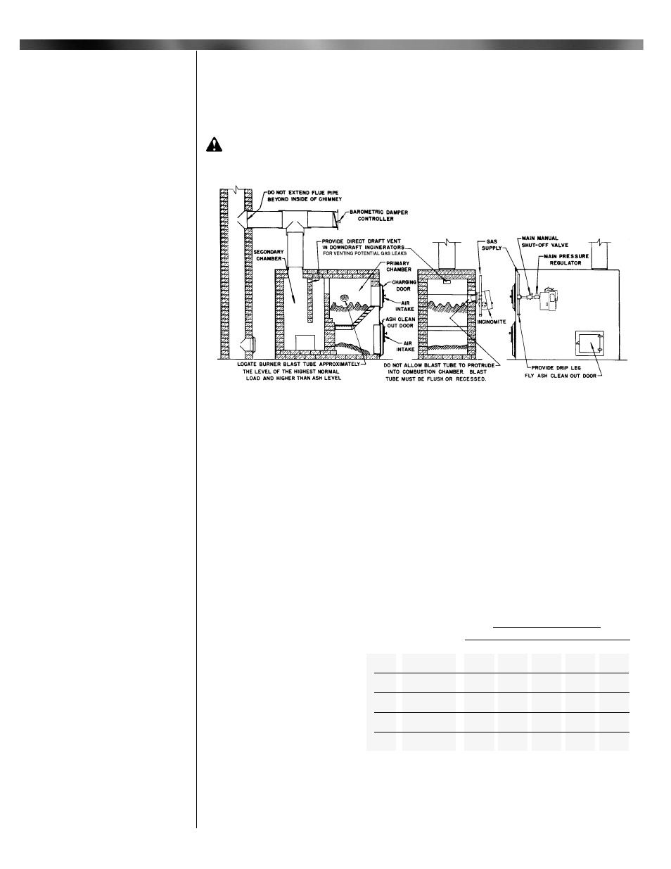
CAUTION: If the incinerator is of the down draft design, make sure that a direct draft
vent opening of approximately 10 square inches has been put through the top of the drop
section(s) to provide for the venting of any gas leakage. See Figure 1.
_________________________________
The size and type of material used for the vent connector and chimney must conform to the rec-
ommendations of the incinerator manufacturer, as well as local and national codes. This is espe-
cially true where high flue gas temperatures are encountered.
When natural draft is used and the chimney height is over 25 feet, a barometric damper of the
same size as the vent connector should be installed. If the chimney is high enough to make it dif-
ficult for the barometric to maintain a maximum incineration chamber over-fire draft, 0 to minus
0.5" W.C., a fixed damper should be installed in the vent connector between the barometric and
chimney to restrict the chimney draft to a point within the controlling capacity of the barometric.
After final setting, the damper should be permanently fastened into position per ANSI Z223.1-lat-
est edition "National Fuel Gas Code", or latest edition available from American National
Standards Institute to prevent tampering.
_________________________________
The supply piping to the burner should branch off from the main line as close to the source as
possible (NATURAL gas meter or
PROPANE tank regulator). When
branching off from an existing gas
line, do not tap o ff the bottom of a
horizontal section. Use new black
pipe and malleable fittings free
from cutting and threading burrs or
defects.
Use pipe joint compound resist-
ant to liquid petroleum gases
when using either NATURAL or
PROPANE gas. Piping must com-
ply with the local and national
codes. If the burner piping must be
rearranged because of space limi-
tations, be sure to carry out the
general configuration shown in
Figure 2.
Figure 1: Typical Installation
V Piping
Capacities shown are for total pressure drop of 0.3”W.C. For
higher permissible pressure drops consult your fuel supplier.
Source: Gas Engineers Handbook-1974
Industrial Press Inc. NY, NY
Table 1: Supply Pipe Capacities in MBH
Type
of
Gas
NATURAL
PROPANE
NATURAL
PROPANE
NATURAL
PROPANE
NATURAL
PROPANE
NATURAL
PROPANE
10
275
450
520
800
800
-
-
-
-
-
20
200
300
350
550
730
800
800
-
-
-
40
130
200
245
385
500
790
760
800
800
-
60
100
165
195
300
400
630
610
800
800
-
100
-
125
150
235
300
480
460
725
800
800
NPT
Pipe
Size
3/4"
1"
1-1/4"
1-1/2"
2
Approximate Capacity - MBH
Length of Pipe / Feet