Iv vent connector continued v electrical – Midco DS24A User Manual
Page 4
IV Vent Connector
Continued
V Electrical
■
■
■
■
The Vent Connector shall be firmly attached to draft hood outlets and flue collars. Joints
between sections of connector piping shall be fastened by sheet-metal screws or other approved
means. The Vent Connector shall be supported for the design and weight of the material
employed to maintain clearance and prevent physical damage and separation of joints.
CAUTION: Do not add any power consuming devices in the low voltage circuit as
overloading of the transformer can result. Do not use Motor Relay to operate any exter-
nal devices as overloading of motor relay contacts can result.
Note: If any of the original wiring as supplied with the conversion burner must be replaced, it
must be replaced with type TFF wire or its equivalent.
Installation wiring and grounding of the burner must conform to local codes, or in their absence
in the United States to National Electric Code, ANSI/NFPA No. 70-latest edition; in Canada,
to Canadian Electrical Code Part 1, CSA Standard C22.1.
■
■
■
■
Use 14 gauge copper wire for line voltage wiring. Be sure to hook up to a permanently live
circuit. Provide a fused on-off disconnect switch carrying a minimum 3 amp fuse.
■
■
■
■
The frame of the burner must be well grounded. A terminal is provided in the control box for
positive grounding where insulated pipe couplings are used or where any doubt exists regarding
grounding sufficiency.
■
■
■
■
Confirm that the polarity is correct—hot wire strip terminal 1, neutral 2— and that the neutral
line is not subject to induced low voltage (check 2 to earth ground) from other equipment as that
can cause the electronic flame safeguard to malfunction.
■
■
■
■
Each installation must include suitable limit controls. Existing oil burner combination limit and
operating controls are normally NOT SUITABLE for gas burner use.
■
■
■
■
Set the thermostat heat anticipator for the total current draw handled by the thermostat. The
current draw of the ECONOMITE 24V operating circuit is 0.9 amps.
CAUTION: Label all wires prior to disconnection when servicing controls. Wiring
errors can cause improper and dangerous operation. Verify proper operation after servic-
ing.
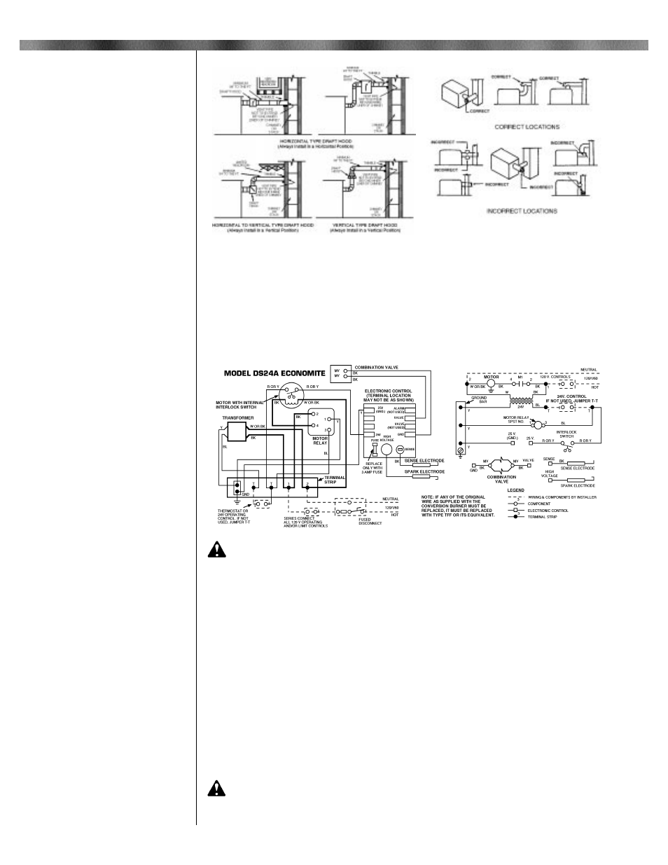
Figure 3: Draft Hoods
Figure 4: Location for Barometric
Draft Regulator
Figures 3 and 4: Copyright by the
American Gas Association. Used by
permission of the copyright holder.
Figure 5: Wiring Diagram
4