Viii initial start-up/adjustment – Midco 400B-33 User Manual
Page 5
*Spud Size and approximate manifold gas pressure
setting; as shipped.
NATURAL gas PROPANE gas
TABLE 3: Spud Capacity and Preliminary Gas Settings
VIII INITIAL START-UP/ADJUSTMENT
WARNING: Ignition is automatic. Make spark
observations into combustion chamber only with
Main and Pilot Manual Shut-Off Valves closed.
Confirm that gas utilization equipment does not
contain any accumulated gases. Purge as described
in Step 3 below.
1.
Check the burner piping and valves for gas leaks by
applying a weak liquid soap solution to unions and
joints with the gas supply on. Leakage will be
indicated by the appearance of soap bubbles. Locate
and correct all gas leaks before proceeding.
WARNING: DO NOT USE OPEN FLAME.
2.
Purging the air from the gas supply line at this step
will expedite first light-off.
IMPORTANT: Purge outside the building.
Do not purge into the gas utilization equipment.
3.
To purge the gas utilization equipment and chimney
of any accumulated gases, turn Manual Gas Cock
Knob on Combination Valve to OFF, close Pilot
Manual Shut-Off Valve, turn burner power on, and
set operating control to ON or thermostat to call for
heat. Let the blower run long enough to accomplish
four air changes, but not less than five minutes.
4.
IMPORTANT:Make sure that the capacity range of
the installed spud and the preliminary combustion
air shutter setting are suitable for capacity rating of
the gas utilization equipment. Refer to Section VII
and Table 3.
5.
RESET
the Electronic Control by setting the
operating control to OFF or the thermostat below
room temperature for at least 30 seconds. See
Section XII.
6.
Confirm the Main and Pilot Manual Shut-Off Valves
are open. Turn Manual Gas Cock Knob on
Combination Valve to ON.
7.
Turn operating control to ON or set thermostat above
room temperature. After a 30 second pre-purge, the
pilot should ignite. Whenever the burner pilot fails to
light during the 15-second ignition trial, or if the
flame is lost during the burner run and is not
re-established within 15 seconds after the pre-purge,
the Electronic Control will shut off the Combination
Valve and LOCK OUT. To RESET the Electronic
Control for restart, de-energize the Electronic Control
by setting the operating control to OFF or thermostat
below room temperature for at least 30 seconds. If
burner still fails to light, turn it off and repeat from
step 5 above. Then if necessary, refer to the
TROUBLE CHART to isolate the problem.
WARNING: Repeated unsuccessful attempts
to light will result in accumulated gases in gas
utilization equipment and chimney. To prevent
these gases from reaching an explosive level,
periodically purge the gas utilization equipment
and chimney as described in step 3 above.
8.
To make a preliminary setting of the burner input,
determine the manifold gas pressure required from
Table 3 and adjust the Combination Valve Main Gas
Pressure Regulator accordingly. See Section XI.
9.
To determine the firing rate for NATURAL gas,
accurately time test dial for the number of seconds
for one revolution and use the following formula. All
other gas utilization equipment must be off.
3600 x test dial size x BTU value
No. of seconds for one rev. test dial
Then divide by 1,000 for MBH value.
Example: 3600 x 1 x 1000
20
For PROPANE gas, consult your supplier for method of
determining firing rate.
10. Adjust combustion air shutter to provide a quiet, soft
blue flame with well defined orange and yellow tips
for NATURAL gas or with well defined yellow tips
for PROPANE gas.
11. The combustion air adjustment which affects the
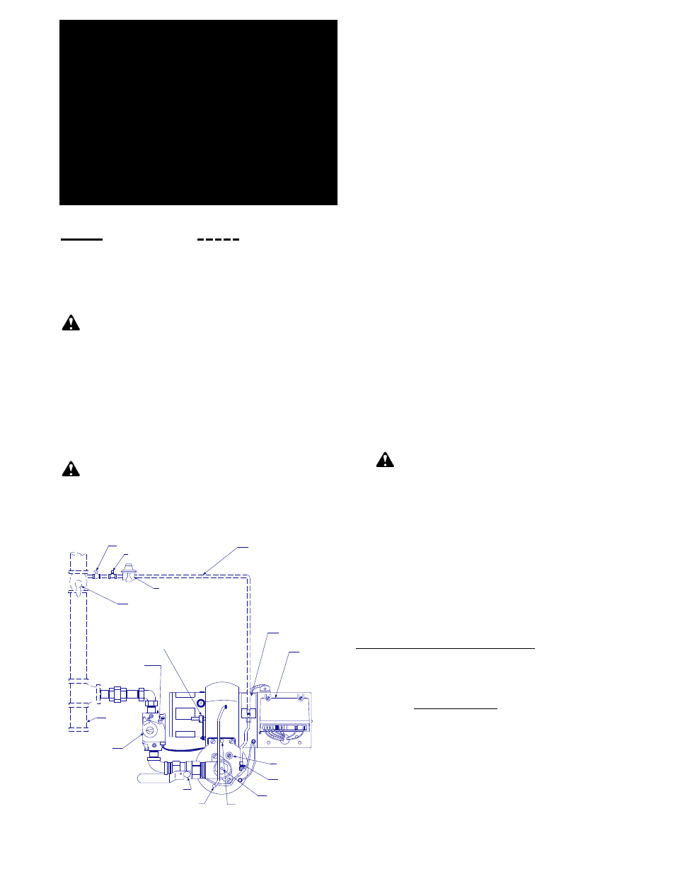
PILOT MANUAL SHUT-OFF VALVE
PILOT REGULATOR
PILOT TUBING
PILOT SOLENOID
ELECTRONIC
CONTROL
PRIMARY AIR
ADJUSTMENT
PILOT GAS
PRESSURE TAP
MANIFOLD GAS
PRESSURE TAP
PEEP SIGHT
PILOT AIR TUBE
BALL VALVE
TEST COCK
MAIN MANUAL
SHUT-OFF VALVE
COMBINATION AIR
CONTROLLING SHUTTER
(COUNTER-CLOCKWISE TO OPEN)
SEDIMENT
TRAP
MANUAL GAS
COCK KNOB
MAIN GAS
PRESSURE
REGULATOR
INLET PRESSURE TAP
1/8 TEE
1/8 PLUG
CONSTRUCTION MAY VARY BY BURNER
APPLICATION REQUIREMENTS
FIGURE 5 Piping Connections
-5-
= BTU/Hr.
=180,000 BTU/Hr. =180