Installation – Midco HMA-2 & HMA-2A Series User Manual
Page 8
8
Midco
International
Inc.
8471 34
NOTE: If burner is over 4′, natural gas, or 5′, propane gas, a back inlet is required as shown
below.
Gas
Inlet
Capacities
Maximum Feet of Burner
Inlet Size
Natural Propane
1.5 ″ NPT End Inlet
4′
5′
2″ NPT Back Inlet
6.5′
8′
Centrally Located
___________________________________
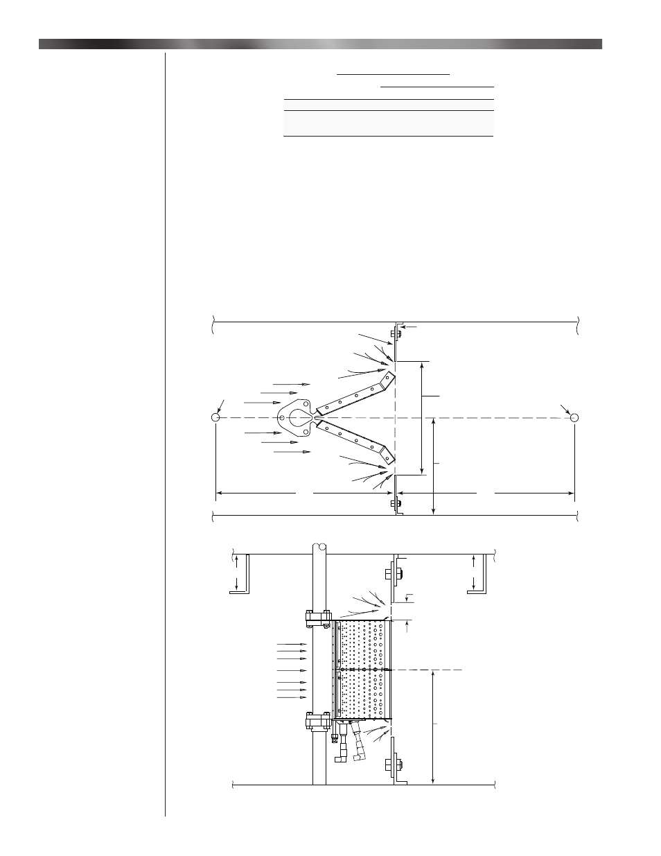
The performance of the HMA-2 & 2A burner depends on the unit in which the burner is located. The
burner can perform differently in different units and can obtain different end results. Maintaining a
relative laminar fl ow around the burner and providing a suffi cient space between the burner and
the blower is a key factor in obtaining best burner performance. The unit should be free of any
obstructions that can create turbulent effect on the air.
Note: Any reinforcements around the profi le plates should be down stream of the profi le plate.
Static pressure probes are needed to sense the differential air pressure across the profi le plates.
The static pressure probes should be installed 12″ upstream from the burner and 12″ downstream
from the burner centrally located in the duct. See Figure 1a and 1b for typical location.
Burner Assembly
Burner Placement
in the Profi le
Installation
Air Flow
Adjustable
Profile Plate
Fixed
Profile Plate
Profile
Opening
should be
Centered to
the Burner
Burner should
be Centered
to the Blower
12"
12"
Static
Pressure
Probe
Static
Pressure
Probe
1" to 4", typical 2"
Air Flow
Burner should
be Centered
to the Blower
4"
4"
Figure 1b - Burner Placement in the Profi le
Figure 1a - Burner Placement in the Profi le
Table 4 - Gas Inlet Capacities